An industrial hydraulic power unit works by converting mechanical power into controlled hydraulic power. In most industrial systems, an electric motor drives a hydraulic pump. The pump draws oil from the reservoir and sends it into the hydraulic circuit. Valves then control the oil direction, pressure, and flow before the oil reaches a cylinder, hydraulic motor, or another actuator.
In simple terms, the hydraulic power unit is the power source of the hydraulic system. It does not do the work by itself. Instead, it supplies pressurized oil so that actuators can lift, press, clamp, push, rotate, or move machine parts. It is commonly used in hydraulic presses, automation equipment, material handling systems, waste compactors, test benches, metallurgical equipment, and other industrial machines.
For industrial equipment, this process must be stable, safe, and repeatable. That is why an industrial hydraulic power unit usually includes not only a motor and pump, but also a tank, valve manifold, filters, cooler, sensors, gauges, and sometimes an electrical control cabinet.
What Is an Industrial Hydraulic Power Unit?
An industrial hydraulic power unit, often called an industrial HPU, is a complete hydraulic power supply system used in machines that require strong and controlled movement. It is commonly used in hydraulic presses, automation equipment, material handling systems, waste compactors, test benches, metallurgical equipment, and other industrial machines.
Compared with a small hydraulic power pack, an industrial hydraulic power unit is usually larger, more configurable, and designed for heavier working conditions. It may need higher flow, larger tank capacity, better cooling, more complex valve functions, and longer duty cycles.
The basic purpose is always the same: provide the correct hydraulic power for the machine’s working requirements.
How Oil Flows Through an Industrial Hydraulic Power Unit
The oil flow path is one of the easiest ways to understand how an industrial hydraulic power unit works. In a typical system, the flow path can be simplified as:
Reservoir → Pump → Pressure Line → Valve Manifold → Actuator → Return Line → Filter / Cooler → Reservoir
First, the electric motor starts and rotates the hydraulic pump. The pump draws hydraulic oil from the reservoir through the suction line and sends it into the pressure line. At this stage, the pump mainly creates flow, not pressure. Pressure is generated when the oil flow meets resistance from the load, cylinder, valve restriction, or machine movement.
After the oil leaves the pump, it passes through the valve manifold. The valves control where the oil goes, how fast it flows, and how much pressure is allowed in the system. The oil then enters the actuator. If the actuator is a hydraulic cylinder, the oil pushes the piston and moves the rod. If the actuator is a hydraulic motor, the oil creates rotation.
After the actuator completes its work, the oil returns to the reservoir through the return line. On the way back, it may pass through a return filter, oil cooler, or other components before entering the tank again. In real industrial systems, the flow path may also include check valves, flow control valves, pressure reducing valves, accumulators, sensors, and other control elements.
Although different machines may use different circuit designs, the basic idea remains the same: hydraulic oil circulates through the system to transfer power, control movement, and return to the tank for repeated operation.
Main Components and Their Functions
An industrial hydraulic power unit is made of several key components. Each one has a specific function.
| Component | Main Function |
|---|---|
| Electric Motor | Provides mechanical power to drive the pump |
| Hydraulic Pump | Converts mechanical rotation into hydraulic oil flow |
| Oil Reservoir | Stores hydraulic oil and helps with cooling and air release |
| Valve Manifold | Controls oil direction, pressure, and flow |
| Relief Valve | Helps protect the system from excessive pressure |
| Filter | Removes contamination from the hydraulic oil |
| Cooler | Helps control oil temperature during operation |
| Pressure Gauge / Sensors | Monitor system pressure, temperature, oil level, or working status |
| Control Cabinet | Controls motor start, valve action, and automatic operation when required |
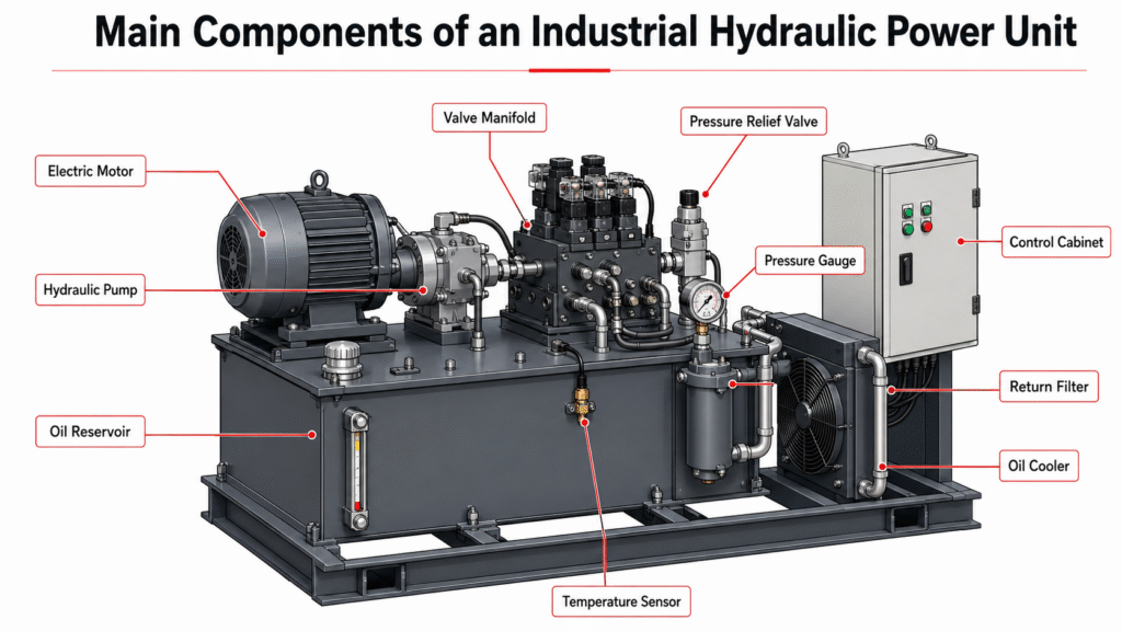
The exact configuration depends on the machine. A simple industrial unit may only need basic directional and pressure control. A more advanced system may need proportional valves, accumulators, PLC control, pressure transducers, cooling units, and multiple pump groups.
How Pressure, Flow, and Valves Control Machine Movement
Pressure, flow, and valves work together to control how a machine moves.
Flow mainly affects actuator speed. For example, a higher flow rate can make a hydraulic cylinder extend or retract faster, if the rest of the system allows it. Pressure is related to force and load resistance. A cylinder needs enough pressure to move the load. When the load increases, system pressure usually rises.
However, higher pressure does not automatically mean faster movement, and larger flow does not automatically mean more force. This is why industrial hydraulic power unit selection should not be based on pressure alone. Engineers also need to consider required flow, motor power, working cycle, oil temperature, actuator size, valve function, and system safety.
Valves make hydraulic power controllable. A directional valve controls where the oil goes. In a cylinder circuit, it can send oil to one side of the cylinder to extend the rod, or to the other side to retract it. A relief valve limits maximum system pressure and helps protect the system from overpressure. A flow control valve can adjust actuator speed, while a check valve can prevent reverse flow.
In more advanced industrial systems, proportional valves may be used for smoother speed and pressure control. Without proper valves, the pump may create flow, but the machine cannot move safely, accurately, or repeatedly.
A stable industrial HPU must match both the force requirement and the speed requirement of the machine, while using the correct valve circuit to control movement.
Why Filtration and Cooling Matter
Industrial hydraulic power units often work under repeated or continuous operating conditions. This makes filtration and cooling very important.
Hydraulic oil carries power, but it can also carry contamination. Dirt, metal particles, or damaged seal material can affect pumps, valves, and cylinders. Filters help keep the oil cleaner and reduce the risk of component damage.
Heat is another common issue. During operation, hydraulic systems generate heat due to pressure loss, flow restriction, friction, and continuous work cycles. If the oil temperature becomes too high, oil viscosity changes and seals may wear faster.
For this reason, many industrial hydraulic power units use return filters, air coolers, oil temperature sensors, and larger reservoirs to support more reliable operation.
Simple Example: Hydraulic Power Unit for a Hydraulic Press
A hydraulic press is a good example of how an industrial hydraulic power unit works.
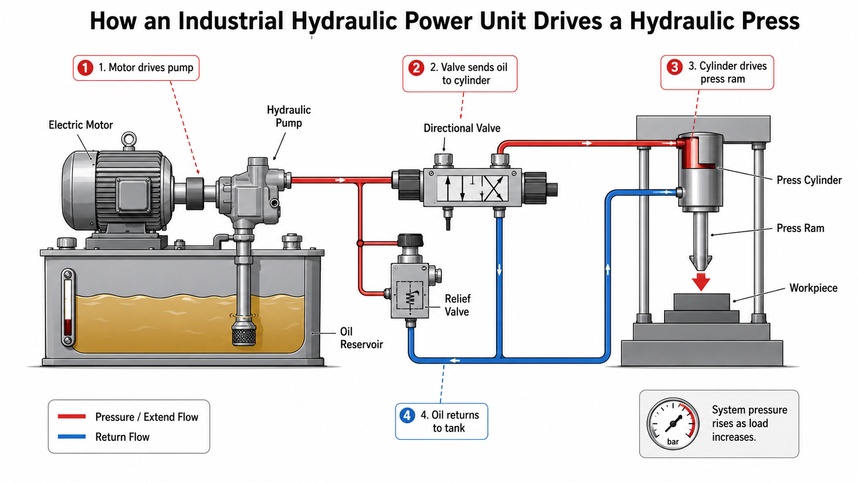
When the operator starts the machine, the electric motor drives the pump. The pump sends oil from the reservoir into the pressure line. A directional valve sends oil to the press cylinder. The cylinder rod moves and pushes the press ram downward.
As the press contacts the workpiece, resistance increases and system pressure rises. The relief valve helps limit the maximum pressure. After the pressing action is complete, the valve shifts, and oil is directed to retract the cylinder. The return oil flows back to the reservoir through the return line and filter.
This process shows the basic logic of most industrial hydraulic systems: the power unit supplies oil, the valves control movement, and the actuator performs the work.
Common Mistakes When Understanding Industrial HPUs
One common mistake is thinking that a larger motor always means a better hydraulic power unit. In reality, motor power must match pressure, flow, and working cycle.
Another mistake is focusing only on working pressure. Pressure is important, but flow, tank capacity, valve function, cooling, filtration, and control method are also critical.
Some buyers also describe the required unit only by tank size, such as “we need a 100-liter hydraulic station.” Tank capacity alone is not enough. Engineers also need to understand the machine type, actuator data, working pressure, flow requirement, voltage, duty cycle, installation space, and working environment.
What Information Is Needed Before Selecting One?
Before selecting or designing an industrial hydraulic power unit, it is helpful to prepare the following information:
- Machine type and application
- Required working pressure
- Required flow rate
- Cylinder bore, rod diameter, and stroke
- Hydraulic motor requirement, if used
- Working cycle and duty condition
- Voltage and electrical requirements
- Valve function and control logic
- Tank capacity or space limitation
- Cooling and filtration requirements
- Hydraulic schematic or equipment drawing, if available
With this information, engineers can better evaluate the pump, motor, tank, valves, cooling system, and overall hydraulic circuit.
Summary
An industrial hydraulic power unit works by using a motor to drive a pump, sending hydraulic oil through valves to actuators, and returning the oil back to the reservoir for repeated circulation. The pump provides flow, the load creates pressure, and the valves control direction, speed, and safety.
For industrial machines, a reliable hydraulic power unit is not just a motor, pump, and tank. It must match the machine’s load, speed, working cycle, control method, cooling needs, filtration requirements, and installation conditions.
FAQ
Does a hydraulic power unit create pressure or flow?
The pump mainly creates flow. Pressure is generated when the flow meets resistance from the load, actuator, or valve restrictions.
Can one industrial hydraulic power unit drive multiple cylinders?
Yes, one industrial hydraulic power unit can drive multiple cylinders if the pump flow, pressure capacity, valve circuit, and control logic are designed correctly.
Why does hydraulic oil return to the tank?
Oil returns to the tank so it can release heat, separate air, settle contamination, and be reused in the next working cycle.
What is the difference between an industrial HPU and a mini hydraulic power pack?
An industrial HPU is usually larger and more configurable. It may include stronger cooling, larger tank capacity, more complex valves, PLC control, and longer duty cycle design. A mini hydraulic power pack is usually more compact and used for smaller or intermittent-duty applications.
Need help understanding or selecting an industrial hydraulic power unit? Send your basic machine requirements, hydraulic schematic, cylinder data, or working cycle. An engineer can help review the pressure, flow, tank capacity, valve function, and control requirements.