Choosing the right hydraulic power unit for a waste compactor is not only about motor power or tank size. A waste compactor needs stable compaction force, controlled ram movement, reliable pressure performance, and safe operation during repeated working cycles.
A hydraulic power unit supplies the oil flow and pressure control required to drive the compaction cylinder. To select the right unit, engineers should consider compaction force, cylinder size, stroke, working pressure, flow rate, duty cycle, oil temperature, filtration, control method, and installation space.
For waste compactor applications, the hydraulic power unit must be designed for repeated cycles, high load resistance, contamination protection, stable pressure, and safe machine control.
How a Hydraulic Power Unit Works in a Waste Compactor
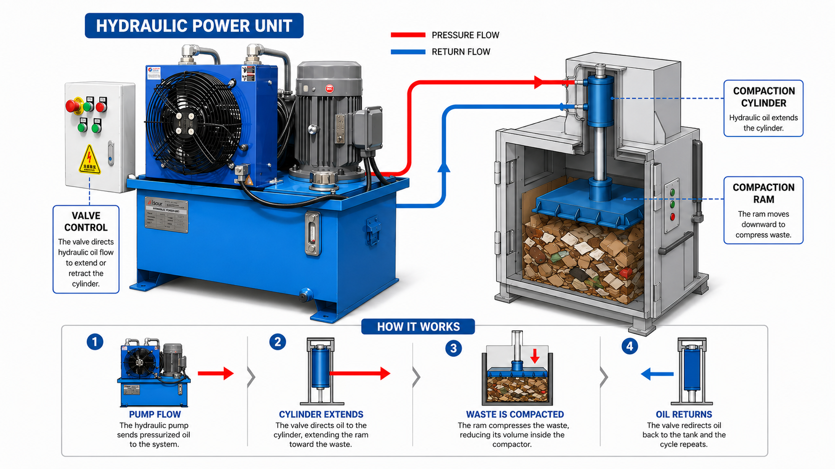
The working process of a hydraulic power unit in a waste compactor is straightforward.
First, the electric motor starts and drives the hydraulic pump. The pump creates oil flow and sends hydraulic oil from the reservoir into the pressure line. The oil then passes through the valve manifold. Depending on the machine cycle, the valve directs oil to the compaction cylinder.
When oil enters the cylinder, the piston moves and drives the compaction ram forward. The ram pushes waste material into the compaction chamber or container. As the waste becomes compressed, resistance increases and system pressure rises. After the compaction stroke is complete, the valve changes position and the cylinder retracts. The return oil flows back to the reservoir through the return line and filter.
The basic cycle is:
Motor starts → Pump creates flow → Valve controls direction → Cylinder extends → Waste is compacted → Cylinder retracts → Oil returns to tank
Although the cycle is simple, the hydraulic power unit must be strong and reliable enough to handle repeated operation, shock load, and changing material resistance.
Why Waste Compactors Need a Reliable Hydraulic Power Unit
Waste compactors often work with mixed materials, irregular loads, and repeated compaction cycles. The load can change from cycle to cycle depending on the material type, moisture content, density, and chamber condition.
If the hydraulic power unit is not properly selected, the compactor may suffer from several problems. The ram may move too slowly if pump flow is not enough. The machine may fail to compact dense material if the system cannot reach the required pressure. Oil temperature may rise if the duty cycle is too heavy or the cooling system is not suitable. Contamination may also affect valves, pumps, and cylinder seals.
A reliable hydraulic power unit helps the waste compactor maintain stable compaction force, controlled ram movement, and repeatable working cycles.
Common Waste Compactor Applications
Hydraulic power units can be used in different types of waste compacting equipment, including:
- Stationary waste compactors
- Self-contained compactors
- Recycling compactors
- Cardboard compactors
- Industrial waste compactors
- Refuse compactors
- Transfer station compactors
- Waste handling equipment
- Mobile waste equipment
- Garbage truck compaction systems
Different machines require different hydraulic power unit designs. A small cardboard compactor may need a compact power unit with simple valve control. A large industrial waste compactor may need a stronger pump, larger oil tank, better filtration, and more robust pressure control. A garbage truck compaction system may require a hydraulic power unit or hydraulic system designed for mobile use and frequent cycles.
Key Components of a Waste Compactor Hydraulic Power Unit
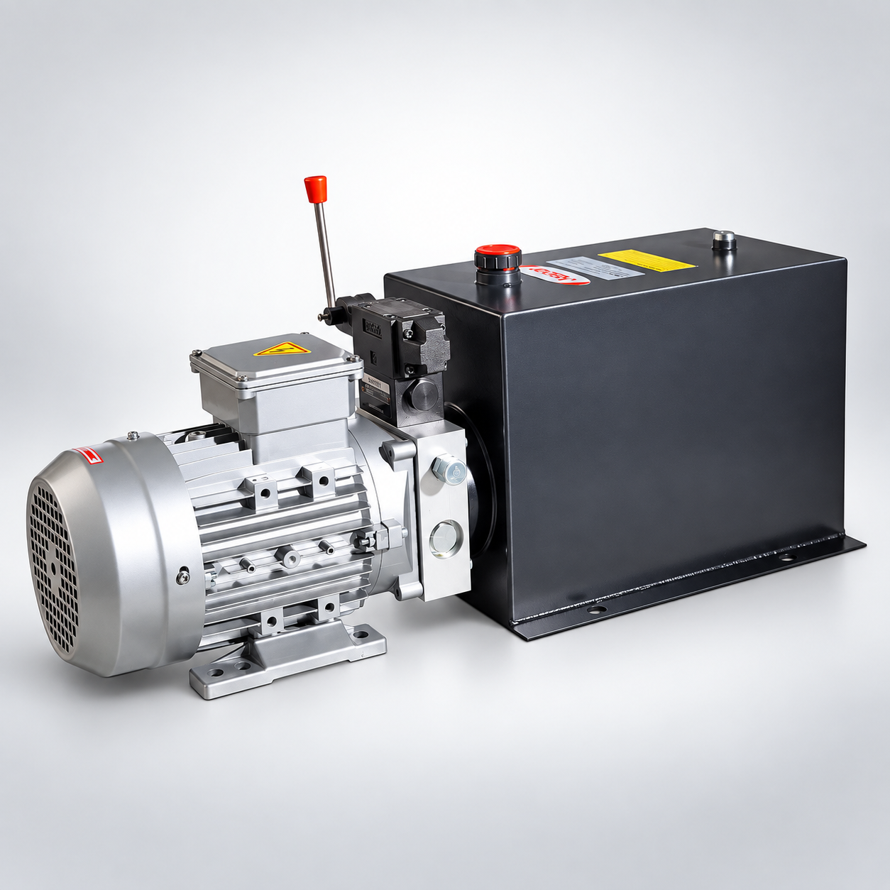
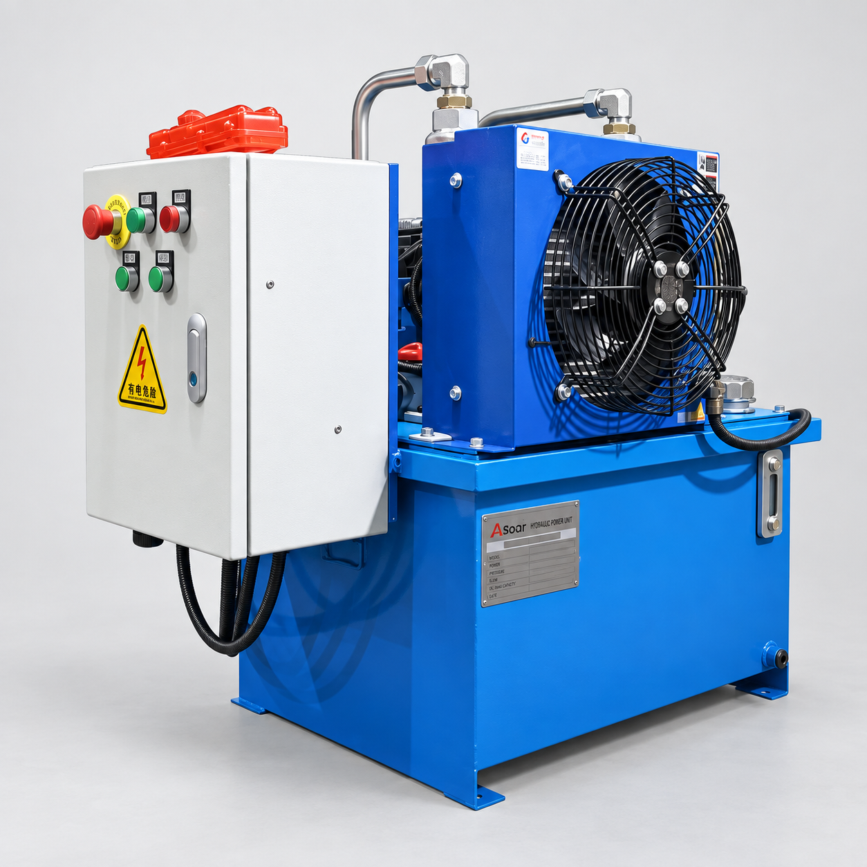
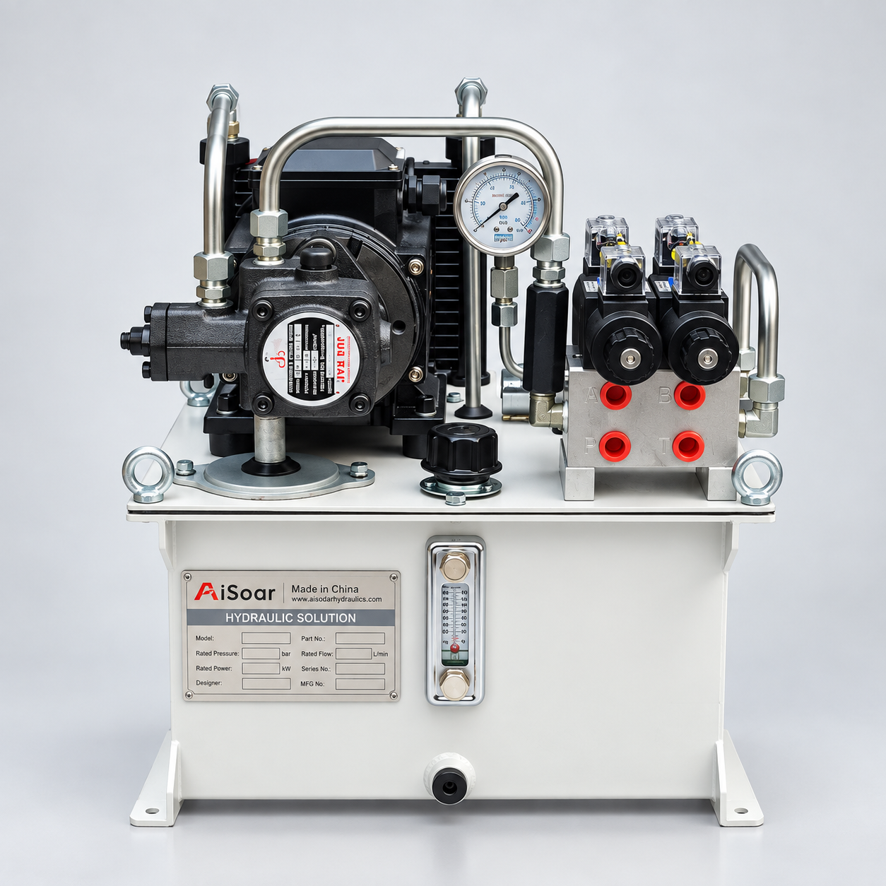
A hydraulic power unit for waste compactors usually includes several important components.
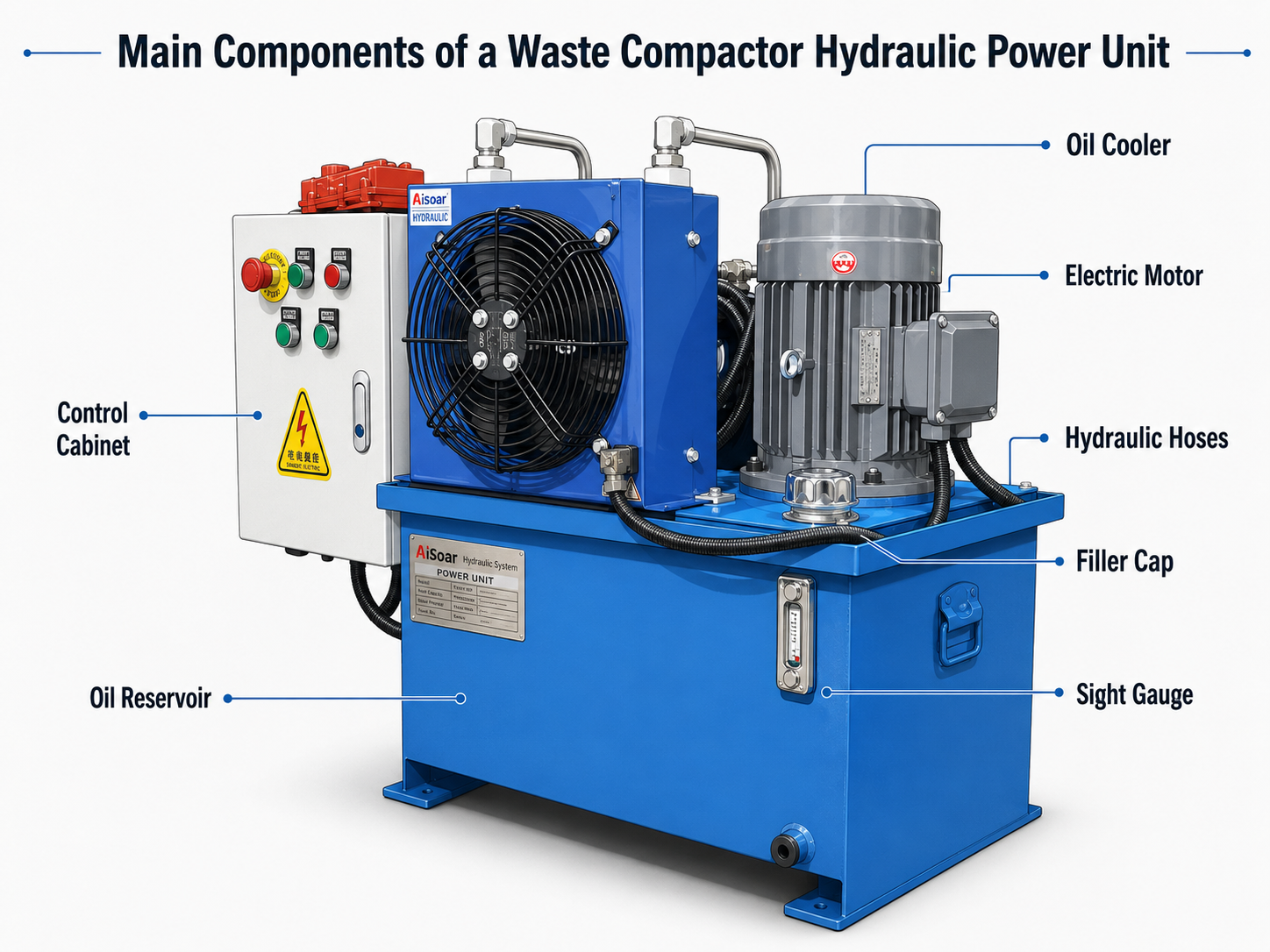
| Component | Function in Waste Compactor Applications |
|---|---|
| Electric Motor | Provides power to drive the hydraulic pump |
| Hydraulic Pump | Supplies oil flow to move the compaction cylinder |
| Oil Reservoir | Stores hydraulic oil and helps with cooling and air separation |
| Directional Valve | Controls cylinder extension and retraction |
| Relief Valve | Helps limit maximum system pressure |
| Check Valve | Helps prevent unwanted reverse flow |
| Flow Control Valve | Helps adjust cylinder speed when required |
| Return Filter | Helps keep hydraulic oil cleaner |
| Oil Cooler | Helps control oil temperature in repeated operation |
| Control Box | Controls motor start, valve operation, and machine cycle |
The exact configuration depends on the compactor structure and control method. Some compactors use a simple hydraulic circuit. Others may require multiple valves, pressure sensors, automatic cycle control, emergency stop logic, oil temperature monitoring, or customized manifold blocks.
Pressure, Flow, and Compaction Performance
Pressure and flow are two important factors in waste compactor performance.
Pressure is related to compaction force. When the ram pushes against waste material, the system must generate enough pressure to move the load. If the material is dense or uneven, resistance may increase and system pressure may rise.
Flow mainly affects cylinder speed. A higher flow rate can move the compaction ram faster, if the cylinder size, valves, hoses, and system design allow it. However, faster movement is not always better. Waste compactors need controlled movement to reduce impact, pressure shock, and mechanical stress.
For this reason, a waste compactor hydraulic power unit should match both the required compaction force and the required cycle speed. The system should also be designed to avoid excessive heat during repeated operation.
Important Design Factors
When selecting a hydraulic power unit for waste compactors, several factors should be considered.
Compaction force requirement
The power unit must support the force needed to compress the target waste material.
Cylinder size and stroke
Cylinder bore, rod diameter, and stroke affect force, oil volume, speed, and total cycle time.
Working pressure
The system pressure must match the load requirement and the hydraulic circuit design.
Flow rate and cycle speed
Pump flow affects ram extension and retraction speed. The flow should match the required working cycle.
Duty cycle
Waste compactors may operate many cycles per day. Motor, pump, tank, and cooling design should match the working frequency.
Oil temperature control
Repeated compaction cycles can generate heat. A suitable tank size, return line design, and cooler may be required.
Contamination protection
Waste handling environments can be dusty and dirty. Good filtration and proper sealing help protect the hydraulic system.
Control method
Manual control, solenoid valve control, pendant control, or automatic PLC control may be used depending on the machine.
Installation space
The hydraulic power unit must fit the compactor structure and maintenance access requirements.
Common Mistakes When Choosing a Waste Compactor HPU
One common mistake is choosing a hydraulic power unit only by motor power. Motor power is important, but it must match pump flow, working pressure, cylinder size, and duty cycle.
Another mistake is ignoring oil temperature. Waste compactors often work in repeated cycles, and heat can build up if the tank, pump, valve circuit, or cooling system is not suitable.
Some buyers also provide only the compactor size or machine photos. This is useful, but not enough for proper selection. Engineers also need the cylinder data, required force, stroke, speed, voltage, control method, and working cycle.
A hydraulic power unit for a waste compactor should be selected according to the actual compaction process, not only by general equipment size.
Information Needed Before Selecting a Waste Compactor HPU
Before selecting or designing a hydraulic power unit for a waste compactor, it is helpful to prepare:
- Type of waste compactor
- Waste material type
- Required compaction force
- Cylinder bore, rod diameter, and stroke
- Working pressure
- Required extension and retraction speed
- Cycles per hour or per day
- Voltage and motor requirements
- Control method
- Tank size or installation space limit
- Cooling requirement
- Filtration requirement
- Hydraulic schematic or machine drawing, if available
With this information, engineers can better evaluate pump flow, motor power, valve function, tank capacity, cooling design, and overall hydraulic circuit.
Summary
A hydraulic power unit is the main power source of a waste compactor. It supplies oil flow, supports pressure generation under load, and allows valves to control the compaction cylinder.
For waste compactor applications, the power unit must be selected according to compaction force, cylinder size, working speed, duty cycle, oil temperature, contamination protection, control method, and installation space.
A properly designed hydraulic power unit helps waste compactors operate with stronger compaction force, smoother ram movement, safer control, and more reliable repeated operation.
Need help selecting a hydraulic power unit for a waste compactor? Send your compactor type, cylinder size, stroke, working pressure, required cycle speed, voltage, and working frequency. An engineer can help review the basic hydraulic power unit configuration for your application.
FAQ
What type of hydraulic power unit is used for waste compactors?
Waste compactors usually use an electric motor-driven hydraulic power unit with a pump, oil tank, valve manifold, pressure control valve, filter, and control system.
Does a waste compactor need high pressure or high flow?
Both may be important. Pressure is related to compaction force, while flow affects ram movement speed and cycle time.
Why does a waste compactor hydraulic power unit overheat?
Possible causes include excessive duty cycle, undersized tank, insufficient cooling, high pressure loss, continuous relief valve operation, or unsuitable pump and valve selection.
Can one hydraulic power unit drive multiple compactor cylinders?
Yes, but pump flow, pressure capacity, valve circuit, synchronization, and control logic must be designed correctly.
What information is needed to quote a waste compactor hydraulic power unit?
Useful information includes compactor type, cylinder bore, rod diameter, stroke, working pressure, speed requirement, voltage, control method, duty cycle, and installation space.