Designing a hydraulic system for high-temperature service is not simply a matter of installing a larger oil cooler or replacing standard seals with heat-resistant materials. A system can still overheat if it wastes power across relief valves, throttling valves, restrictive lines, or worn components.
The objective is to reach a stable thermal balance under the real operating cycle. Heat generated by the pump, valves, pipes, actuators, and internal leakage must be equal to or lower than the heat released through the reservoir, cooler, piping, and surrounding air. The oil must also remain within a viscosity range that allows the system to operate efficiently.
These elements should therefore be designed as one thermal system.
Start with the Actual Operating Cycle
The first step is to define what “high temperature” means for the machine. Ambient temperature, reservoir oil temperature, and local component temperature are not the same.
A power unit operating outdoors at 40°C may experience much higher temperatures inside a closed enclosure or beside an engine or exhaust pipe. Hoses and solenoid valves near a local heat source may also operate well above the reservoir temperature.
The complete operating cycle matters more than maximum pressure and flow alone. A lower-pressure system that continuously throttles a large volume of oil may generate more heat than one that reaches high pressure for only a few seconds.
Before design begins, confirm the ambient-temperature range, expected oil temperature, continuous runtime, pressure-holding duration, average and peak flow, cycle frequency, idle periods, external heat sources, and available ventilation or cooling water.
Identify and Reduce the Main Heat Sources
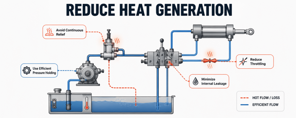
Hydraulic heat is mainly input power that is not converted into useful mechanical work. During preliminary design, the heat load can be estimated by comparing pump input power with the useful power delivered by the actuators. The difference is released through pressure losses, leakage, friction, and fluid agitation.
On an existing machine, pressure and temperature measurements can help locate losses. A large pressure drop across a valve, filter, cooler, hose, or quick coupling indicates continuous energy loss. A hot pump case drain or return branch may indicate declining efficiency, throttling, or bypass flow.
Continuous relief-valve flow is one of the most common causes of overheating. When a fixed-displacement pump continues supplying full flow after an actuator has stopped, or when pump output exceeds machine demand, the excess oil returns to the tank across a pressure drop. Almost all of that unused power becomes heat.
For variable demand, a variable-displacement, pressure-compensated, or load-sensing pump may reduce unnecessary flow. In a fixed-displacement system, an unloading circuit can keep the pump at low pressure during idle periods.
Maintaining a load by running the pump continuously at high pressure is also inefficient. Depending on the application, the load may instead be held with a check valve, counterbalance valve, accumulator, low-flow holding circuit, or mechanical lock.
These losses should be reduced before the cooler is selected. Otherwise, the cooling system may be sized to remove heat that a better circuit could have prevented.
Design the Pipework and Reservoir as Thermal Components
Pipe diameter should be selected from actual flow, acceptable oil velocity, and allowable pressure loss rather than component port size alone. Suction lines should be short, direct, and large enough to protect the pump from inlet restriction. Pressure and return lines should be checked at maximum flow, including temporary peaks caused by cylinder area ratios or accumulator discharge.
Return-line resistance is often underestimated. If oil passes through a small hose, restrictive fitting, filter, cooler, and several elbows in series, the pump must generate additional pressure simply to return the oil to the tank. That pressure loss becomes heat and can increase backpressure at cylinders, motors, and valve drains.
The reservoir supports heat release and air separation as well as oil storage. For continuous high-temperature operation, it needs sufficient effective volume, good airflow, controlled return velocity, and a clear operating level range.
The return and suction connections should be separated by a baffle so that hot aerated oil does not return directly to the pump. The reservoir should also be positioned away from engines, exhaust systems, furnaces, and other heat sources whenever possible.
Select the Cooler from the Required Heat Rejection
A cooler should be selected according to the heat that remains after avoidable circuit losses have been reduced. Pump flow and port size alone do not define cooling capacity.
Required heat rejection depends on thermal load, target oil temperature, maximum ambient temperature, duty cycle, oil flow through the cooler, and the available cooling medium. A practical margin is needed for fouling, higher summer temperatures, increased cycles, and gradual efficiency loss.
Air-cooled coolers are common on mobile equipment and systems without a dependable water supply. Their performance depends on incoming-air temperature, fan airflow, fin cleanliness, and installation position. Hot discharge air must leave the enclosure rather than circulate back through the cooler.
Water-cooled heat exchangers are often suitable for stationary, continuous-duty systems with higher thermal loads. Cooling-water temperature, flow, water quality, scaling, and maintenance access must also be considered.
The cooler circuit must be checked for cold-start viscosity, pressure rating, bypass protection, fan or water-valve control, and pressure loss at maximum flow. An oversized cooler cannot correct continuous relief flow, excessive throttling, or severe internal leakage.
Match the Fluid and Components to Continuous Temperature
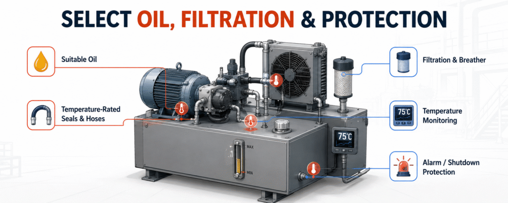
Hydraulic oil must maintain suitable viscosity from the lowest startup temperature to the highest stabilized operating temperature. Oil that is too viscous increases suction resistance and pressure loss. Oil that becomes too thin increases internal leakage and weakens lubrication in pumps, valves, cylinders, and motors.
Oil selection should consider viscosity grade, viscosity index, oxidation stability, air release, foam resistance, demulsibility, and seal compatibility. High-temperature oil may improve viscosity retention and service life, but it cannot compensate for an inefficient circuit or inadequate cooling.
Seals, hoses, accumulators, solenoid coils, sensors, connectors, and electronic modules should be selected using continuous temperature ratings rather than short-duration peak values. Fluid compatibility, movement speed, pressure pulsation, and radiant heat should also be considered.
Where components cannot be relocated, local heat shields, insulating sleeves, improved ventilation, or revised hose routing may be more effective than specifying higher-temperature components throughout the system.
Integrate Cleanliness, Monitoring, and Protection
High temperature accelerates oil oxidation and contamination-related wear. Filtration should be sized for actual hot-oil flow and selected according to the cleanliness requirement of the most sensitive component. Undersized filters can create excessive pressure drop during cold start or peak return flow.
The design should also include a suitable reservoir breather, filtered oil filling, water and condensation control, drain and cleaning points, oil-sampling ports, and differential-pressure indicators.
Temperature monitoring should be included from the beginning. The reservoir is the normal reference point, but measurements at the cooler inlet and outlet, pump case drain, main return line, or enclosed power-unit compartment can provide better diagnostic information.
The control system should act before the oil reaches its maximum permitted temperature. It may start the fan, open cooling-water flow, issue an alarm, reduce cycle frequency, limit high-load movement, or stop the system. Alarm and shutdown settings should reflect the actual limits of the oil and installed components.
Verify the Design Under the Real Duty Cycle
A high-temperature design is not complete until it has been tested under conditions close to actual service.
The system should run through its normal pressure, flow, speed, holding time, and cycle frequency while temperatures are recorded at defined intervals. The key result is whether the oil temperature stabilizes. A temperature that continues rising after several hours shows that heat generation still exceeds heat rejection.
During the test, record motor current, system pressure, actuator speed, cooler inlet and outlet temperatures, pump case-drain temperature, return-line backpressure, and changes in leakage or control stability. Cooling-fan operation, alarms, derating logic, and shutdown protection should be verified.
After the system cools, check the oil level, filters, hoses, fittings, and external leakage again. Comparing hot and cold performance can reveal viscosity-related leakage, thermal expansion, and restrictions that may not appear during short commissioning tests.
Information Required Before Final Design
A complete proposal should be based on the ambient-temperature range, pressure and flow requirements, actuator loads and speeds, movement sequence, cycle frequency, continuous runtime, holding requirements, fluid type, installation space, external heat sources, ventilation, contamination exposure, and available cooling conditions.
Providing the complete duty cycle is more useful than supplying only maximum pressure, pump flow, and motor power. High-temperature reliability depends on how the machine uses hydraulic power over time.
Conclusion
Reliable high-temperature hydraulic system design begins with energy efficiency and thermal balance. The designer must understand the real operating cycle, reduce unnecessary pressure and flow losses, and then size the reservoir and cooler for the remaining heat load.
The pump, valves, manifold, pipes, filters, reservoir, cooler, oil, seals, hoses, sensors, and control system should be evaluated together. When the completed system is tested under the actual duty cycle and the oil temperature reaches a stable level with sufficient margin, it is far more likely to maintain consistent pressure, speed, efficiency, and service life during summer and other high-temperature conditions.