Designing a hydraulic system should begin with the machine requirements rather than with a pump, valve or hydraulic power unit selected from a catalog. Before choosing any hydraulic component, it is important to understand how much force the machine needs, how fast the actuator must move, how often the system will operate and what level of control and safety is required.
These requirements determine the actuator size, working pressure, flow demand, pump capacity, valve configuration and hydraulic circuit architecture. A practical hydraulic system design process can be summarized as:
Load Requirements → Actuator → Pressure → Flow → Pump & Motor → Valves → Circuit Architecture → System Verification
Define the Hydraulic System Requirements
The first step is to define exactly what the hydraulic system must do. For a cylinder-based system, the main information normally includes required force, stroke, movement speed, duty cycle, number of actuators, operating sequence and available power supply. The working environment and required control method should also be considered.
Two machines may require the same cylinder force but still need very different hydraulic systems. For example, one machine may operate only several times per hour while another works continuously. Their force requirement may be identical, but their pump, motor, reservoir and cooling requirements can be very different.
For this reason, hydraulic system design should be based on the complete machine cycle rather than only the maximum load.
Determine Hydraulic Cylinder Force and Actuator Size
For a hydraulic cylinder, the basic force relationship is:
F = P × A
where F is cylinder force, P is hydraulic pressure and A is the effective piston area.
The actual design force should normally include a suitable margin for friction, mechanical losses, acceleration and changing load conditions. If a machine requires approximately 65 kN of design force and the selected working pressure is 160 bar, the required piston area can be calculated from:
A = F ÷ P
This gives a theoretical bore of approximately 72 mm. In practice, a standard bore such as 80 mm may be selected after checking available cylinder sizes, mounting space and the required safety margin.
Cylinder bore and system pressure should always be considered together. A larger cylinder can produce more force at the same pressure, but it also requires more oil to achieve the same movement speed.
Calculate Hydraulic System Pressure and Flow
Pressure and flow play different roles in a hydraulic system. Pressure is mainly related to the load the actuator can overcome, while flow is mainly related to actuator speed.
Once the cylinder size has been selected, the required flow can be calculated from:
Q = A × v
where Q is flow, A is effective piston area and v is piston speed.
For an 80 mm bore cylinder moving at 0.1 m/s, the theoretical flow requirement is approximately 30 L/min. In a real system, pump efficiency, internal leakage and circuit losses should also be considered.
This relationship is important during troubleshooting as well. If a cylinder has enough force but moves too slowly, increasing pressure is usually not the correct solution. The available flow and any restrictions in the hydraulic circuit should be checked instead.
Select the Hydraulic Pump and Motor
After the required pressure and flow are known, the hydraulic pump can be selected. The pump must provide enough flow for the target actuator speed while operating reliably at the required system pressure.
Gear pumps are commonly used in relatively simple hydraulic systems, while vane or piston pumps may be selected where higher pressure, better efficiency, lower noise or variable flow is required. The correct pump type depends on the complete application rather than pressure alone.
Hydraulic power can be estimated using:
Hydraulic Power (kW) = Pressure (bar) × Flow (L/min) ÷ 600
If the system operates at 160 bar and 30 L/min, the theoretical hydraulic power is approximately 8 kW. The actual motor should provide additional capacity to compensate for pump and mechanical efficiency losses, while also considering peak load and duty cycle.
Pump selection should therefore come after the actuator requirements have been established, not before.
Choose the Right Hydraulic Valves
Once the power requirements are defined, the next step is controlling where the oil goes and how the actuator behaves. A typical hydraulic system may require pressure-control, directional-control, flow-control and load-control valves.
A relief valve limits the maximum system pressure, while a directional valve controls cylinder extension and retraction. Flow-control valves can regulate actuator speed, and check valves prevent unwanted reverse flow. Systems with suspended or overrunning loads may also require pilot-operated check valves or counterbalance valves.
Valve selection should not be based only on port size. Pressure rating, flow capacity, pressure drop, leakage characteristics and control method can all affect hydraulic system performance. An undersized valve may create unnecessary pressure loss, reduce available actuator power and generate additional heat.
Select the Hydraulic Circuit Architecture
After the pump, actuator and valve functions are defined, the complete hydraulic circuit architecture can be selected. The correct architecture depends on machine complexity, number of functions, required control accuracy and energy-efficiency targets.
An open-center hydraulic system normally allows pump flow to return to the reservoir when the directional valve is in neutral. It is commonly used with fixed-displacement pumps and is suitable for many simple mobile and industrial systems.
A closed-center hydraulic system controls or blocks the main flow path differently when the machine is not moving. These systems are often combined with pressure-compensated or variable-displacement pumps and are useful where more complex control is required.
A load-sensing hydraulic system adjusts pump output according to the pressure and flow demand of the active function. This can reduce unnecessary energy consumption, especially in machines where the load and required flow change frequently.
The most advanced circuit is not always the best choice. The architecture should match the actual operating requirements, cost target and required level of control.
Check the Complete Hydraulic System Design
After the main circuit has been designed, supporting components also need to be verified. The reservoir must provide sufficient working oil volume and support heat dissipation and air separation, while filtration should match the cleanliness requirements of the pump and control components.
Hoses, pipes, fittings and manifolds should be sized to avoid excessive pressure loss. If the flow path is too restrictive, available actuator power decreases and more hydraulic energy is converted into heat.
Thermal performance also needs to be checked against the actual duty cycle. Continuous operation, excessive throttling, relief-valve losses and internal leakage can all increase oil temperature. All pressure-containing components should also be rated safely above the expected operating conditions.
Hydraulic System Design Example
Consider a machine with the following requirements:
| Parameter | Example |
|---|---|
| Required design force | 65 kN |
| Working pressure | 160 bar |
| Cylinder bore | 80 mm |
| Cylinder stroke | 500 mm |
| Target speed | 0.1 m/s |
| Required flow | Approx. 30 L/min |
| Theoretical hydraulic power | Approx. 8 kW |
The design sequence would be:
Machine Load → Cylinder Selection → Operating Pressure → Required Flow → Pump Selection → Motor Selection → Valve Functions → Hydraulic Circuit → System Verification
The important point is that these parameters are connected. If the cylinder bore changes, required pressure and flow may also change. If the target speed increases, pump flow and motor power may need to increase. If the duty cycle changes from intermittent to continuous operation, cooling requirements may become more important.
Hydraulic system design is therefore an iterative process rather than a simple component-selection exercise.
Common Hydraulic System Design Mistakes
One common mistake is selecting the pump first and then trying to design the rest of the hydraulic system around it. Another is focusing only on maximum pressure while ignoring required flow, speed and duty cycle.
Oversizing can also create problems. A pump that provides much more flow than the machine actually needs may increase motor power, create unnecessary throttling and generate more heat.
A better approach is to treat force, pressure, flow, speed, power and control as connected hydraulic system design variables.
Conclusion: Building a Well-Matched Hydraulic System
A hydraulic system should be designed from the machine requirements backward. First determine the required load and movement, then select the actuator and working pressure, calculate the required flow, choose the pump and motor, define the valve functions and select the appropriate circuit architecture.
Finally, verify the reservoir, filtration, pressure losses, temperature and safety requirements. When these elements are correctly matched, the hydraulic system can deliver the required force, speed and control without unnecessary oversizing or energy loss.
Need a Custom Hydraulic System?
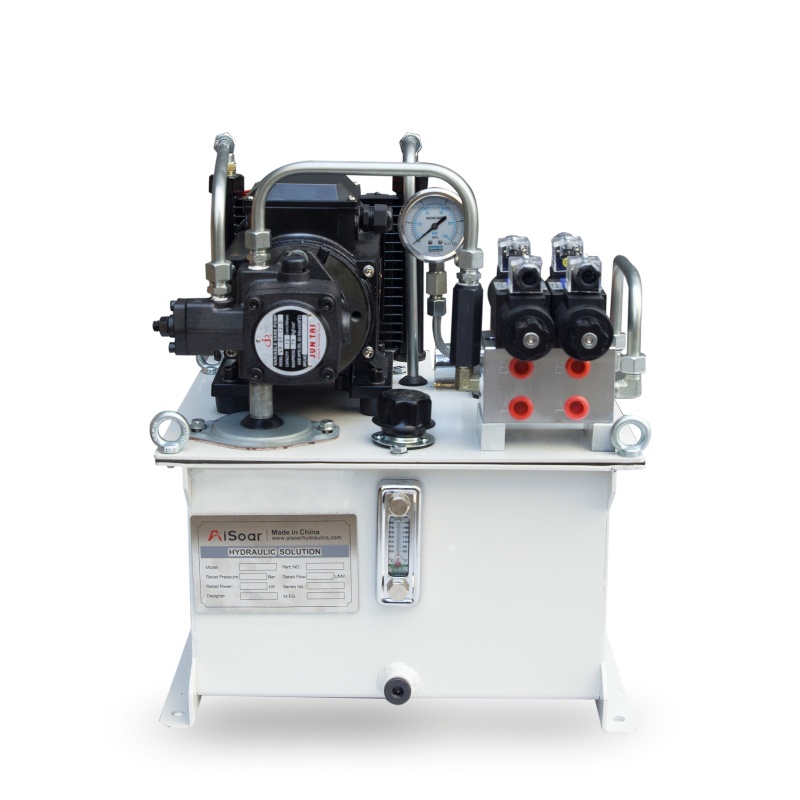
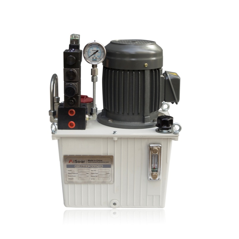
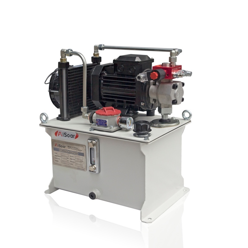
AISOAR provides customized hydraulic power units and hydraulic system solutions for industrial and mobile equipment. System configurations can be developed according to required pressure, flow, cylinder specifications, duty cycle, control method, electrical supply and machine operating conditions.
For a new OEM project, providing the machine load, cylinder specifications, target movement speed and working cycle can help our engineering team evaluate an appropriate hydraulic system configuration.