When a hydraulic system begins to overheat, installing a larger oil cooler is often the first solution considered. However, a cooler can only remove heat that has already been generated.
If the system still has continuous relief valve flow, excessive throttling, serious internal leakage, high return-line backpressure, or undersized piping, increasing cooler capacity may only reduce the oil temperature temporarily. The underlying energy losses will continue producing heat.
Improving hydraulic system cooling therefore requires work in two directions:
- Reducing unnecessary heat generation inside the hydraulic circuit
- Improving heat removal through the reservoir, cooler, airflow, and surrounding environment
Only when the system’s heat generation and heat dissipation are properly balanced can the oil temperature stabilize at a reasonable level during continuous operation.
Reduce Internal Heat Generation First
Before upgrading the cooling equipment, inspect the hydraulic system for unnecessary energy losses.
Whenever pressurized oil passes through a relief valve, a heavily restricted control valve, an undersized pipe, or a worn hydraulic component, part of the hydraulic energy is converted into heat. If these heat sources are not corrected, the cooling system must continuously handle an unnecessarily high thermal load.
Important areas to inspect include:
- Whether the relief valve remains open for long periods
- Whether a fixed-displacement pump continuously supplies oil at high pressure
- Whether a flow control or proportional valve regulates high flow through a very small opening
- Whether the pump or control valves have excessive internal leakage
- Whether return-line pressure is too high
- Whether filters or oil passages inside the cooler are restricted
- Whether pipes, hoses, fittings, or quick couplings have insufficient flow capacity
If the pump outlet pressure is significantly higher than the actual pressure required by the actuator, the difference may indicate excessive throttling, backpressure, or relief losses.
Eliminating these losses is usually more effective than simply installing a larger cooler. It can also reduce energy consumption, pump load, and component wear.
Select the Cooler According to the Actual Heat Load
A hydraulic oil cooler should not be selected according to system flow alone.
The correct cooler size depends on how much heat the hydraulic system actually generates and how much of that heat must be removed to maintain the target oil temperature.
Cooler selection should consider:
- Actual system heat generation
- Normal and maximum oil temperatures
- Maximum ambient temperature
- Continuous operating time
- Oil flow through the cooler
- Hydraulic oil viscosity
- Available installation space
- Airflow or cooling-water conditions
- External heat sources around the machine
An air cooler that performs well at an ambient temperature of 20°C may provide significantly less effective cooling when the surrounding temperature reaches 40°C.
For this reason, cooler selection should be based on the highest expected summer temperature and the machine’s actual continuous-duty cycle. A cooler selected only from short-duration testing may be insufficient once the equipment operates for several hours under full load.
A suitable safety margin should also be considered when operating conditions vary significantly or when the cooler may gradually lose efficiency because of contamination.
Choose Between Air Cooling and Water Cooling
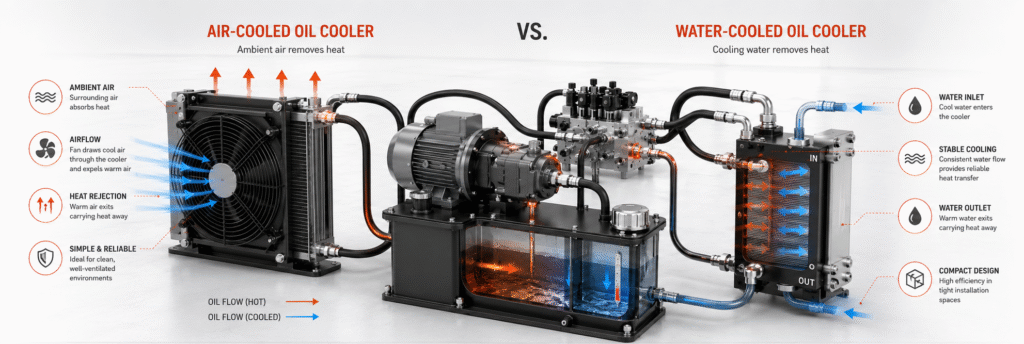
The two most common hydraulic oil cooling methods are air cooling and water cooling. Each has advantages and limitations.
Air-Cooled Oil Coolers
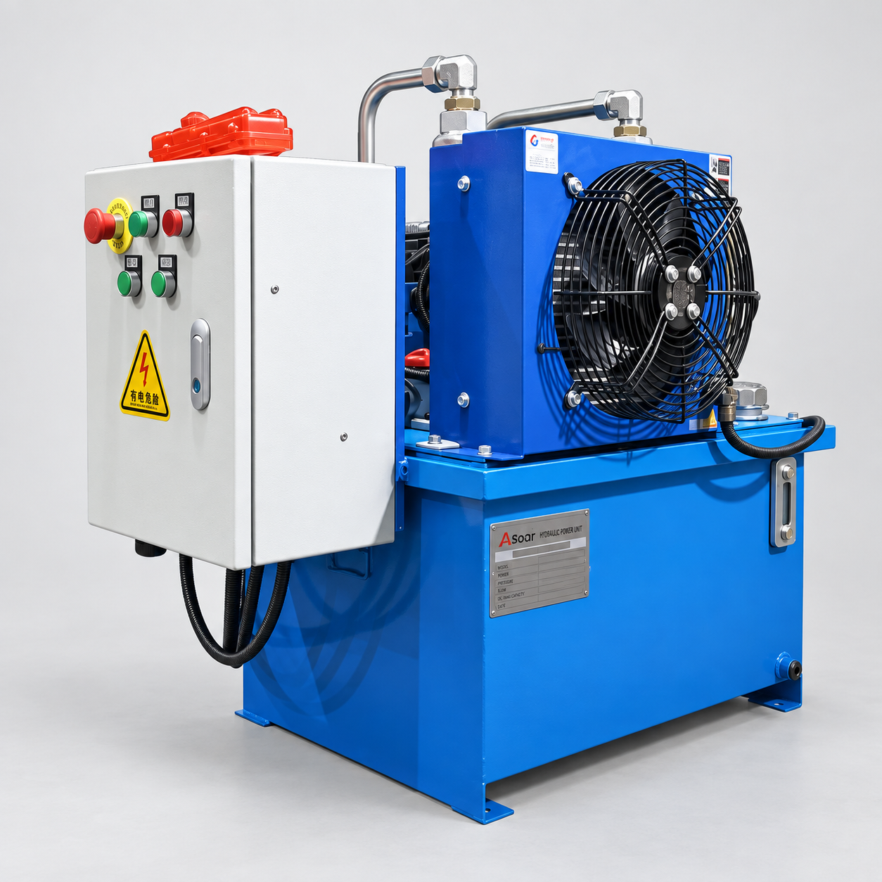
Air-cooled oil coolers are relatively easy to install and do not require an external water supply. They are commonly used on mobile machinery, vehicles, compact hydraulic power units, and independent hydraulic systems.
However, their actual cooling performance is strongly affected by:
- Ambient air temperature
- Fan airflow
- Cleanliness of the cooling fins
- Ventilation around the equipment
- Recirculation of discharged hot air
- Cooler installation position
The cooler should be installed where fresh air can enter freely and hot air can leave the machine enclosure. It should not be positioned close to an engine exhaust, radiator discharge, furnace, or other high-temperature component.
Water-Cooled Oil Coolers
Water-cooled oil coolers are more compact and can usually provide more stable heat transfer under continuous high-load conditions or in hot environments.
Before using a water cooler, confirm:
- Cooling-water inlet temperature
- Available water flow
- Water pressure
- Water quality
- Risk of scale formation
- Internal corrosion risk
- Possibility of oil-to-water leakage
For stationary factory equipment, water cooling is often suitable when a continuous supply of clean, stable-temperature cooling water is available.
However, poor water quality can cause scale deposits inside the cooler. These deposits reduce heat-transfer efficiency and increase water-side resistance. Regular inspection and cleaning are therefore necessary.
Keep the Cooler Clean
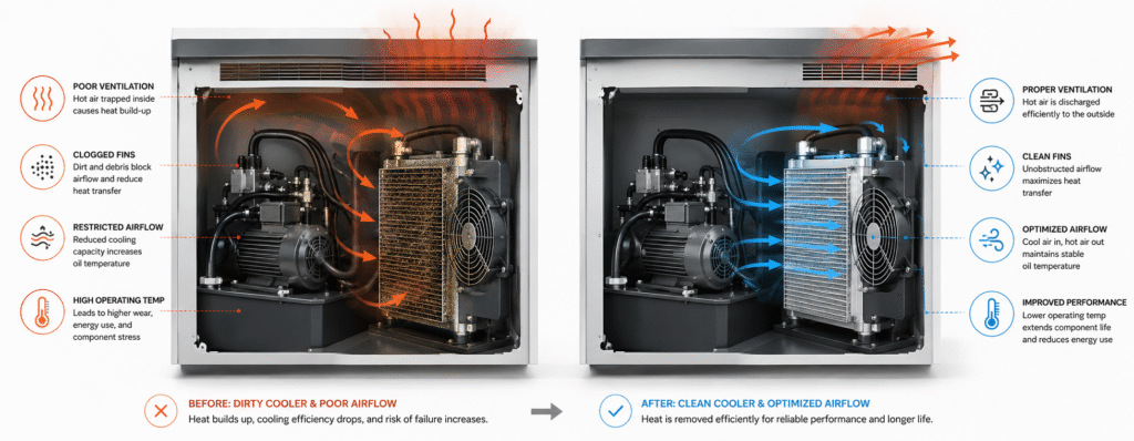
Cooler contamination is one of the most common reasons for gradually declining cooling performance.
On an air cooler, dust, oil mist, fibers, mud, and other debris may collect between the fins. The fan may still rotate normally, but the actual volume of air passing through the heat exchanger can become severely restricted.
During maintenance, inspect:
- Whether the cooling fins are blocked
- Whether the fins are bent or damaged
- Whether the fan rotates in the correct direction
- Whether the fan reaches its normal speed
- Whether the fan motor is overheating
- Whether there is enough open space in front of and behind the cooler
When cleaning the fins, avoid using excessively high-pressure water or compressed air directly against the surface. This can bend the fins and further reduce airflow.
For a water-cooled unit, inspect the water passages for scale, sediment, corrosion, and biological contamination. Internal deposits act as an insulating layer and can significantly reduce heat transfer even when the external surface appears clean.
The oil side should also be checked for sludge, varnish, and other deposits that may restrict oil flow.
Improve Airflow Around the Cooler
Cooling performance depends not only on the size of the heat exchanger but also on whether air can move through and away from it effectively.
If the cooler is installed inside a closed compartment, hot air discharged by the fan may remain inside the enclosure. The cooler may then draw this heated air back through the fins, creating a recirculation loop.
This may cause:
- A gradual increase in cooler inlet air temperature
- Reduced heat-transfer capacity
- Normal temperature shortly after startup but overheating after continuous operation
- Higher temperatures around the electric motor and electrical components
Possible improvements include:
- Adding larger air inlet and outlet openings
- Installing ducting or an air guide
- Directing discharged hot air outside the machine enclosure
- Separating the cooler inlet from the hot-air outlet
- Adding ventilation fans to the compartment
- Changing the cooler installation direction
- Removing obstacles that restrict airflow
Ideally, fresh air should pass through the hydraulic oil cooler before reaching engines, electric motors, exhaust components, or other heat sources.
The cooler should not receive air that has already been heated by another component.
Optimize Reservoir Capacity and Internal Design
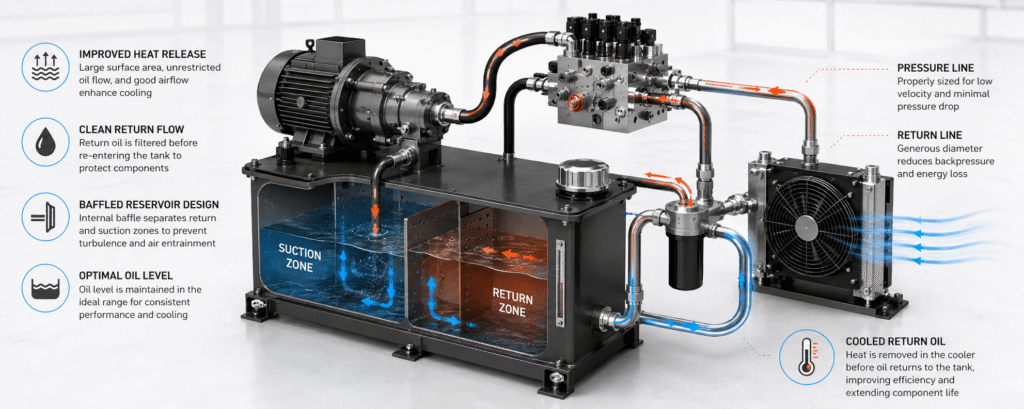
The hydraulic reservoir is not only used to store oil. It also contributes to cooling, air release, contaminant settling, and water separation.
If the effective reservoir volume is too small, the oil may return to the pump before it has enough time to release heat and entrained air.
Important reservoir design factors include:
- Effective oil capacity
- External surface area
- Position of the suction and return ports
- Internal baffle arrangement
- Return-oil velocity
- Normal oil level
- Ventilation around the reservoir
The return line should not discharge high-velocity oil directly onto the oil surface. This can increase aeration and foaming.
Hot return oil should also not flow directly into the pump suction area. A properly designed baffle increases the oil travel path inside the tank, giving the fluid more time to cool, release air, and allow heavier contaminants to settle.
However, a larger reservoir does not automatically guarantee better cooling.
If the tank is installed in a hot, enclosed, or poorly ventilated area, its natural heat dissipation will still be limited. Reservoir location and surrounding airflow are therefore just as important as tank volume.
Reduce Pressure Losses in Pipes and Return Lines
Pressure losses in hydraulic pipes, hoses, fittings, filters, and coolers are ultimately converted into heat.
The following items should be checked:
- Pressure-line diameter
- Return-line diameter
- Suction-line size
- Hose length
- Number of elbows and fittings
- Flow capacity of quick couplings
- Filter rated flow
- Oil-side pressure drop across the cooler
Return-line design is often overlooked.
If the return pipe is too small, or if the return oil must pass through a filter, cooler, several fittings, and restrictive connectors in series, the backpressure may become excessive.
The hydraulic system then requires additional pressure simply to push the oil back to the reservoir. This extra pressure represents wasted energy and additional heat.
Pipe and hose sizes should be selected according to the maximum actual flow, allowable oil velocity, and acceptable pressure drop. The thread size of a port alone does not always indicate the true internal flow area.
Pressure measurements taken before and after filters, coolers, and other return-line components can help identify excessive resistance.
Optimize the Pump and Control Circuit
For continuously operating or frequently cycling equipment, circuit optimization can significantly reduce heat generation.
Possible solutions include:
- Using a variable-displacement pump to match the required flow
- Using a load-sensing system to reduce unnecessary pressure
- Adding a suitable unloading circuit to a fixed-displacement pump system
- Using pressure switches to control pump start and stop
- Using an accumulator during long pressure-holding periods
- Reducing the amount of flow controlled by throttling
- Improving flow distribution between multiple actuators
- Preventing the pump from remaining at high-pressure standby unnecessarily
Consider a machine that spends much of its operating time waiting or performing low-flow movements. If the pump continues to deliver full flow during these periods, most of the excess hydraulic energy may be converted into heat through valves and restrictions.
Matching pump output to the actual demand can lower oil temperature while also reducing motor power consumption and operating costs.
Isolate External Heat Sources
Some hydraulic systems do not generate excessive internal heat, but their installation environment continuously transfers heat into the reservoir, hoses, valve blocks, and other components.
Common external heat sources include:
- Engines
- Exhaust pipes
- Furnaces
- Heating equipment
- Hot materials
- Electric motors
- Direct sunlight
Possible protective measures include:
- Installing heat shields
- Relocating the reservoir or valve block
- Protecting hoses with high-temperature insulating sleeves
- Moving the cooler away from the heat source
- Adding a sunshade
- Improving enclosure ventilation
- Preventing hot air from blowing directly onto the hydraulic power unit
Thermal insulation should be designed carefully. A heat shield that blocks the normal ventilation path may create a new overheating problem.
The goal is to reduce radiant and convective heat transfer without restricting the airflow required for cooling.
Add Temperature Monitoring and Automatic Control
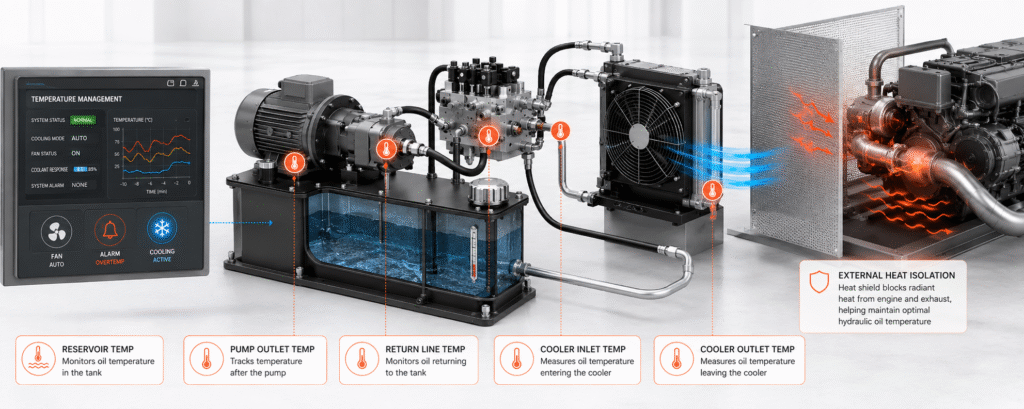
Manual temperature checks may not be sufficient for continuously operating, heavily loaded, or unattended hydraulic equipment.
Temperature sensors can be installed at several locations, including:
- Reservoir
- Pump outlet
- Main return line
- Cooler inlet and outlet
- Valve manifold
- Pump case drain
- Enclosed machine compartment
The control system can then respond automatically by:
- Starting the cooling fan
- Opening the cooling-water supply
- Reducing the machine cycle frequency
- Switching to a lower-load operating mode
- Activating a high-temperature alarm
- Stopping the machine when the temperature becomes unsafe
The fan start temperature, alarm temperature, and shutdown limit should be based on the hydraulic oil, pump, seals, hoses, and overall system design.
A single universal temperature setting should not be used for every hydraulic system.
Temperature trends are often more useful than one isolated reading. A gradual increase in operating temperature over several weeks may indicate cooler contamination, increasing internal leakage, fan deterioration, or declining system efficiency.
Regularly Verify Cooling Performance
Checking whether the fan is rotating is not enough to confirm that the cooling system is working effectively.
The following operating data should be recorded and compared:
| Inspection Item | Main Purpose |
|---|---|
| Ambient temperature | Confirms the actual cooler operating environment |
| Reservoir oil temperature | Shows the overall system temperature trend |
| Cooler inlet temperature | Indicates the thermal load entering the cooler |
| Cooler outlet temperature | Shows the oil temperature after cooling |
| Cooler inlet-to-outlet temperature difference | Helps evaluate heat-transfer performance |
| Oil-side pressure drop | Identifies possible restriction or internal blockage |
| Fan current and speed | Confirms whether the fan is operating correctly |
| Cooling-water inlet and outlet temperatures | Evaluates water-side heat transfer |
| Continuous operating time | Confirms whether the system reaches a stable thermal balance |
If the temperature difference between the cooler inlet and outlet gradually decreases, possible causes include insufficient airflow, low cooling-water flow, contaminated fins, scale deposits, or internal fouling.
However, a small temperature difference does not always mean the cooler is defective. It may also occur when oil flow through the cooler is very high or when the system is generating relatively little heat.
The temperature difference must therefore be evaluated together with oil flow, ambient temperature, total oil temperature, pressure drop, and machine operating conditions.
Conclusion
Improving hydraulic system cooling requires more than simply installing a larger oil cooler.
The most effective approach is to first reduce unnecessary heat generation caused by continuous relief flow, excessive throttling, internal leakage, pressure losses, and return-line backpressure. The reservoir, oil cooler, airflow, piping, control circuit, and temperature monitoring system can then be optimized according to the actual thermal load.
For continuous-duty equipment, oil temperature, pressure, flow, cooler inlet and outlet temperatures, and operating time should be recorded under real working conditions.
This information helps confirm whether the hydraulic system can reach a stable thermal balance during summer or other high-temperature operating conditions.
By controlling both heat generation and heat dissipation, equipment manufacturers and operators can reduce hydraulic oil degradation, limit seal and component wear, improve energy efficiency, and increase the reliability of the entire hydraulic system.