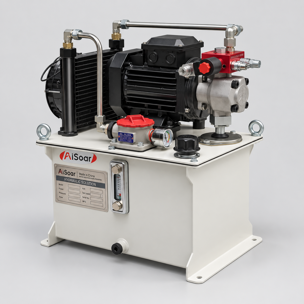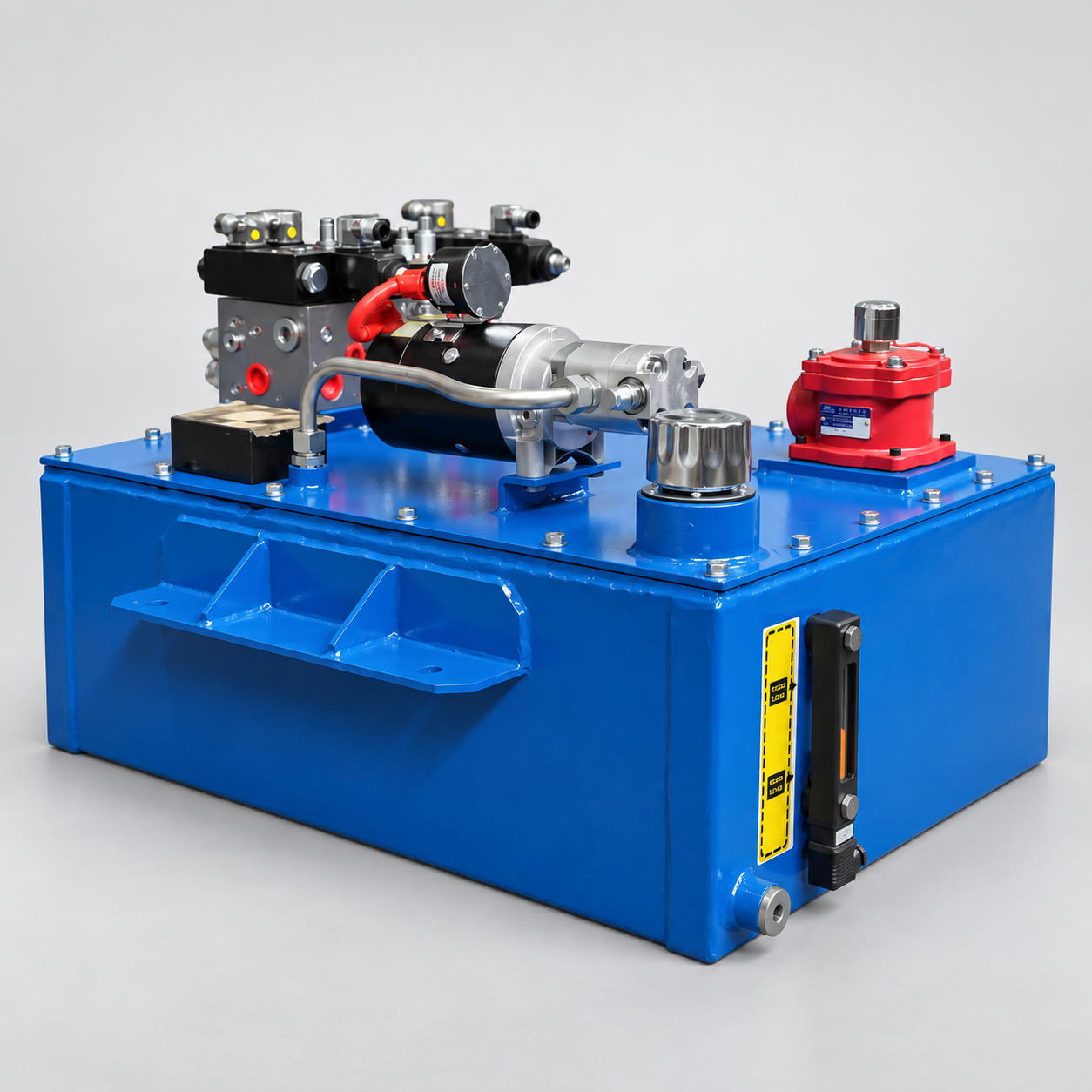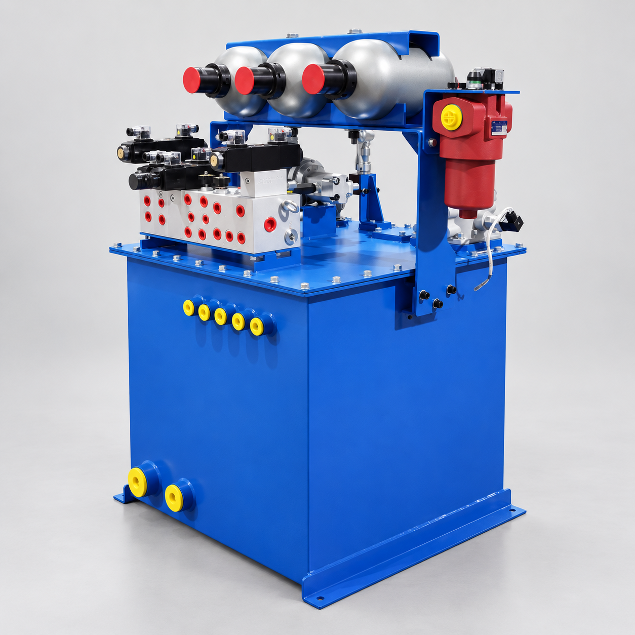
A hydraulic press is normally powered by an Industrial Hydraulic Power Unit, also commonly called a hydraulic station or hydraulic power station. Compared with a Mini Hydraulic Power Unit, a press hydraulic station usually requires a larger reservoir, higher motor power, more complex valve control, better cooling, and a higher duty-cycle capability. The hydraulic power unit generates pressure, controls cylinder movement, maintains pressing force, and supports each stage of the working cycle. If the unit is undersized, the press may move slowly, fail to reach the required force, or overheat. If it is oversized, the machine may consume unnecessary energy and cost more than required.
Selecting the right Industrial Hydraulic Power Unit is not simply a matter of choosing a pump and motor. The complete unit must match the press tonnage, cylinder dimensions, working speed, pressure-holding time, duty cycle, control sequence, and operating environment.
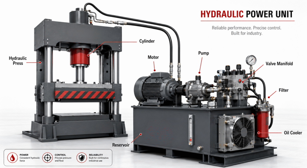
Calculate the Pressure and Force Required by the Hydraulic Press
The first step is to confirm the maximum force the press must produce. Press capacity is commonly stated in tons or kilonewtons, but the hydraulic system should be calculated from the cylinder bore and working pressure.
Cylinder force is determined by hydraulic pressure multiplied by the effective piston area. A larger cylinder can produce the same force at a lower pressure, while a smaller cylinder requires higher pressure.
The calculation should allow for mechanical friction, pressure losses, tooling resistance, and a reasonable safety margin. The maximum system pressure must also remain within the rated limits of the cylinder, pump, valves, hoses, seals, and pipework.
Do not select a hydraulic power unit only from the advertised tonnage of the press. The cylinder drawing and actual force requirement are more reliable engineering inputs.
Example: Calculating Force, Flow, and Motor Power for a Hydraulic Press
The relationship between cylinder size, hydraulic pressure, flow rate, and motor power can be illustrated with a simple example.
Assume that a hydraulic press uses a cylinder with a bore diameter of 250 mm and a maximum working pressure of 200 bar.
The cylinder area can be calculated as:
Cylinder Area = π × Bore² ÷ 4
Since a 250 mm bore is equal to 25 cm:
Cylinder Area = 3.1416 × 25² ÷ 4 ≈ 490.9 cm²
The theoretical pressing force is:
Pressing Force (kN) = Pressure (bar) × Cylinder Area (cm²) ÷ 100
Therefore:
Pressing Force = 200 × 490.9 ÷ 100 ≈ 981.8 kN
This is approximately equal to 100 metric tons of pressing force. In an actual hydraulic press, mechanical friction, pressure losses, and the required safety margin should also be considered.
The required hydraulic flow depends on the target cylinder speed:
Flow (L/min) = Cylinder Area (cm²) × Speed (cm/s) × 0.06
If the cylinder must approach the workpiece at 50 mm/s, or 5 cm/s:
Approach Flow = 490.9 × 5 × 0.06 ≈ 147.3 L/min
However, if the pressing speed is only 5 mm/s, or 0.5 cm/s:
Pressing Flow = 490.9 × 0.5 × 0.06 ≈ 14.7 L/min
This means the press requires approximately ten times more flow during fast approach than during the actual high-pressure pressing stage.
Motor power can be estimated using:
Motor Power (kW) = Pressure (bar) × Flow (L/min) ÷ 600 ÷ Total Efficiency
Assuming a total hydraulic efficiency of 85%, the approximate motor power required during the pressing stage is:
Motor Power = 200 × 14.7 ÷ 600 ÷ 0.85 ≈ 5.8 kW
If the system had to provide the full approach flow of 147.3 L/min at 200 bar, the required motor power would increase to approximately 57.8 kW. In most hydraulic presses, however, maximum pressure and maximum flow are not required at the same time.
During fast approach, the cylinder normally operates at high flow but relatively low pressure. During pressing, it operates at high pressure but much lower flow.
For this reason, hydraulic presses commonly use:
- A high-low dual-pump circuit
- A variable-displacement piston pump
- An accumulator-assisted circuit
- Separate fast-approach and pressing-speed control
These configurations allow the hydraulic power unit to provide fast cylinder movement without requiring an unnecessarily large motor or continuously generating excessive heat.
Calculate the Hydraulic Pump Flow for Each Press Cycle
As the example above shows, a hydraulic press usually requires different flow rates during fast approach, pressing, pressure holding, decompression, and return. Therefore, pump flow should be calculated for each stage of the operating cycle rather than from a single maximum cylinder speed.
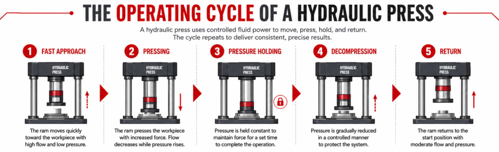
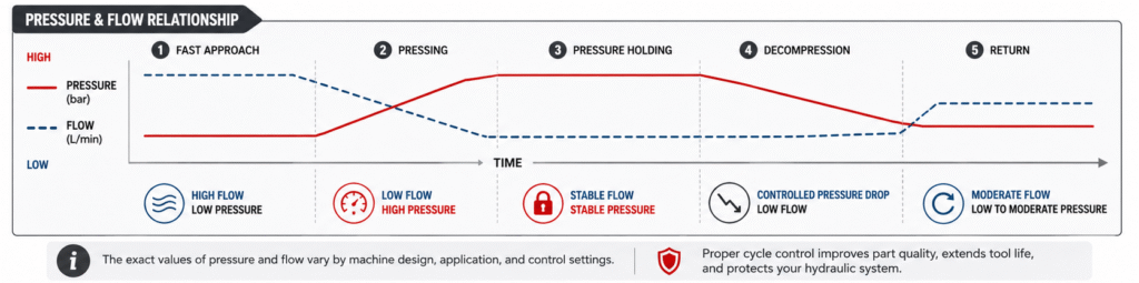
Most hydraulic presses do not operate at one constant speed. A typical working cycle includes:
- Fast approach
- Slow pressing
- Pressure holding
- Decompression
- Fast return
Each stage may require a different combination of pressure and flow.
The required flow is calculated from the cylinder area and target movement speed. A large cylinder may need high flow during fast approach but only low flow during high-pressure pressing.
A single fixed pump selected for the maximum movement speed may waste energy and generate excessive heat during the pressing stage. Depending on the operating cycle, the system may use a dual-pump circuit, variable-displacement pump, accumulator-assisted circuit, or proportional flow control.
The objective is to provide sufficient flow during fast movement while avoiding unnecessary high-pressure flow during the pressing and holding stages. The pump and hydraulic circuit should therefore be selected from the complete pressure-flow cycle rather than from only the maximum pressure or maximum speed.
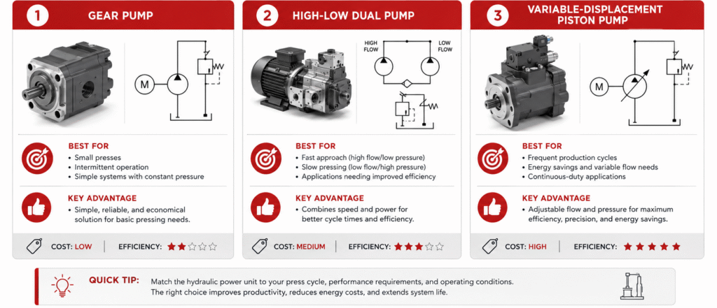
Select the Right Hydraulic Pump for the Press
Common pump options for hydraulic presses include gear pumps, vane pumps, and piston pumps.
Gear pumps are economical and suitable for many standard presses with moderate pressure and intermittent operation. They have a relatively simple structure and are easy to maintain.
Vane pumps provide smoother flow and lower operating noise within suitable pressure ranges. They may be selected for presses where stable movement and lower noise are important.
Axial piston pumps are often used for high-pressure, continuous-duty, variable-flow, or energy-efficient hydraulic press systems.
A variable-displacement piston pump can reduce its output after the required pressure is reached, lowering energy loss and heat generation. However, it is generally more expensive and requires better oil cleanliness than a basic gear pump.
The appropriate pump and circuit configuration also depends on how the hydraulic press operates:
| Hydraulic Press Requirement | Recommended Hydraulic Configuration |
|---|---|
| Small press with intermittent operation | Fixed-displacement gear pump |
| Fast approach and slow high-pressure pressing | High-low dual-pump circuit |
| Frequent production cycles | Variable-displacement piston pump |
| Long pressure-holding time | Pump unloading circuit with pressure-holding valves |
| High-speed, short-duration movement | Accumulator-assisted circuit |
| Precise force and speed control | Proportional or servo-controlled hydraulic system |
| Continuous high-duty operation | Variable pump with enhanced cooling and filtration |
Pump selection should consider:
- Continuous and peak pressure
- Required flow range
- Pump efficiency
- Operating noise
- Hydraulic oil viscosity
- Contamination sensitivity
- Expected service life
- Replacement-part availability
The pump should not operate continuously at its absolute maximum pressure or flow rating. A suitable operating margin helps improve reliability and service life.
Match Motor Power to the Actual Press Cycle
The electric motor must provide enough power to drive the pump under the actual pressure and flow combinations required by the press cycle. As shown in the calculation example, maximum pressure and maximum flow may occur during different stages, so they should not automatically be combined when sizing the motor.
Oversizing the motor in this way can increase purchase cost, electrical demand, and energy consumption without improving the actual pressing performance.
In many hydraulic presses, high flow is required during the low-pressure approach stage, while high pressure is required during the low-flow pressing stage. A correctly designed hydraulic circuit can therefore reduce the required motor power without reducing press performance.
The hydraulic power unit supplier should review the duration of every stage in the working cycle before selecting the motor.
The motor specification should also match the local electrical supply and operating environment, including:
- Voltage and frequency
- Rated motor power
- Motor speed
- Insulation class
- Protection level
- Starting method
- Local electrical standards
Some hydraulic press power units use a variable-frequency drive to improve speed control or reduce energy consumption. However, the drive, motor, pump, and control strategy must be selected as a complete system.
Determine the Hydraulic Reservoir and Cooling Capacity
The hydraulic oil reservoir does more than store oil. It also helps release heat, separate air, settle contaminants, and provide a stable oil supply to the pump.
An undersized tank can lead to rapid oil temperature rise, foaming, air entrainment, poor contaminant separation, and unstable pump inlet conditions.
Reservoir capacity should be selected according to:
- Pump flow
- Total cylinder oil volume
- Press duty cycle
- Cooling requirements
- Available installation space
There is no single reservoir-size rule suitable for every hydraulic press. The final capacity should be verified from oil volume changes, heat balance, air-release time, maintenance space, and the expected duty cycle.
A production press operating continuously normally requires greater reservoir and cooling capacity than an occasional-use workshop press.
Heat is generated by pump inefficiency, internal leakage, pressure losses, and throttling across control valves. If the reservoir cannot dissipate enough heat naturally, the hydraulic power unit may require an air-oil cooler or water-oil cooler.
The reservoir should also include practical maintenance features such as an oil level and temperature indicator, breather filter, drain port, cleaning cover, and correctly arranged suction and return connections.
Select the Hydraulic Valves and Control Method
The hydraulic valve manifold controls cylinder direction, speed, pressure, holding, and decompression. Its configuration must match the actual operating sequence of the hydraulic press.
A hydraulic press power unit may include:
- Directional control valves
- Pressure relief valves
- Check valves
- Pilot-operated check valves
- Pressure-reducing valves
- Unloading valves
- Flow control valves
- Proportional pressure or flow valves
For pressure-holding applications, internal valve leakage must be carefully controlled. For long pressure-holding periods, the pump should not necessarily remain continuously loaded. A properly designed circuit may use pilot-operated check valves, low-leakage cartridge valves, accumulators, or pump unloading control to maintain pressure while reducing energy consumption and heat generation.
Pressure loss during holding may be caused by cylinder seal leakage, valve leakage, oil compression, hose expansion, or changes in oil temperature. The allowable pressure drop and required holding time should therefore be specified before the hydraulic circuit is designed.
For a press that changes from fast approach to slow pressing, the hydraulic circuit must switch smoothly without creating sudden cylinder movement or pressure shock.
Large, high-pressure cylinders may require controlled decompression before the directional valve changes position. This is especially important when the cylinder contains a large volume of compressed oil or when the press holds high pressure for an extended period.
Poor decompression design can create pressure shock, noise, pipe vibration, and damage to valves, seals, or connecting components. Decompression should therefore be considered during the initial hydraulic system design rather than added later.
Specify Filtration and Oil Cleanliness
Hydraulic presses may use precision valves, pressure sensors, and high-pressure pumps that are sensitive to contamination.
Return-line filtration is common in hydraulic power units, while pressure-line or offline filtration may be added for more demanding applications. Filter condition indicators help maintenance personnel replace the filter element before the system enters bypass.
The required oil cleanliness level should be based on the most contamination-sensitive component in the system.
However, filtration alone cannot keep the system clean. Clean assembly, proper reservoir sealing, system flushing, correct oil filling, and controlled commissioning are equally important.
For critical production equipment, high-precision components, or hydraulic presses operating continuously, online oil cleanliness monitoring may also be integrated into the hydraulic station or machine control system.
Include Pressure Monitoring and Hydraulic Safety Functions
A hydraulic press can store significant hydraulic and mechanical energy. The hydraulic power unit must respond safely during normal operation, power failure, emergency stop, hose failure, or control signal loss.
Typical protection and monitoring functions include:
- Main pressure relief protection
- Pressure sensor and mechanical pressure gauge
- Motor overload protection
- Low oil level alarm
- High oil temperature alarm
- Controlled pressure release
- Safe cylinder-holding function
- Emergency-stop interface
- Safety guard and door interlock signals
Applicable machinery, hydraulic, and electrical safety requirements should be reviewed according to the press structure, control method, operating environment, and target market.
Consider the Type of Hydraulic Press
Different types of hydraulic presses can require very different hydraulic power unit configurations.
A small workshop press may use a relatively simple gear-pump system because the machine operates intermittently and does not require complex speed control. A production forming press may require fast approach, controlled pressing speed, pressure holding, decompression, and rapid return.
A baling or compression press may require long strokes, large oil volumes, and extended pressure-holding periods. A precision assembly press may need proportional pressure control, accurate displacement feedback, and repeatable force control.
Multi-cylinder hydraulic presses may also require flow dividers, position sensors, proportional valves, or closed-loop control to maintain cylinder synchronization.
Before selecting the hydraulic power unit, the supplier should therefore understand whether the equipment is a workshop press, forming press, baling press, compression molding press, assembly press, or multi-cylinder press.
What Information Is Needed to Select a Hydraulic Press Power Unit?
To receive an accurate hydraulic power unit proposal, buyers should provide the following information:
| Required Information | Why It Matters |
|---|---|
| Required pressing force | Determines the required system pressure and cylinder force |
| Cylinder bore and rod diameter | Used to calculate force and oil flow |
| Cylinder stroke | Determines oil displacement |
| Approach, pressing, and return speeds | Determines flow for each stage |
| Pressure-holding time | Affects valve leakage and unloading design |
| Cycles per hour | Affects heat generation and cooling |
| Motor voltage and frequency | Determines electrical configuration |
| Control method | Determines valves, sensors, and PLC functions |
A cylinder drawing, hydraulic schematic, or press cycle chart can greatly improve selection accuracy and reduce the risk of incorrect component sizing.
Conclusion
AiSoar Hydraulics designs and manufactures customized Industrial Hydraulic Power Units for hydraulic presses, forming machines, balers, assembly equipment, and other industrial applications.
To receive a suitable hydraulic station proposal, please provide the required pressing force, cylinder bore, rod diameter, stroke, approach speed, pressing speed, return speed, pressure-holding time, duty cycle, and motor voltage. Our engineers can review the complete working cycle and recommend the appropriate pump, motor, reservoir, valve manifold, cooling, filtration, and control configuration.