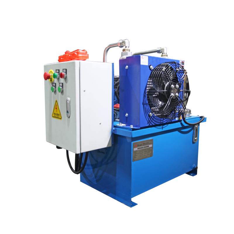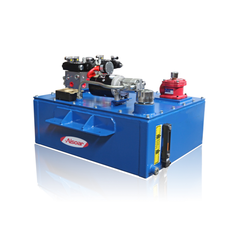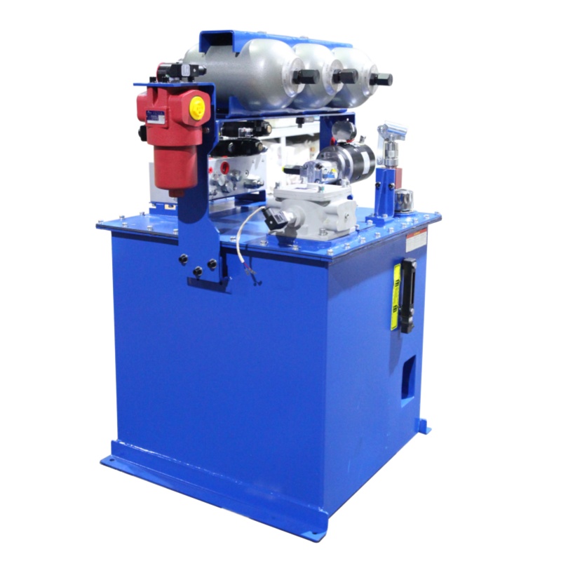
A hydraulic system uses pressurized fluid to transmit power and control mechanical motion. It can generate linear movement through hydraulic cylinders or rotary movement through hydraulic motors, making hydraulics widely used in industrial machinery, mobile equipment, agricultural machines, lifting systems, presses and automated production equipment.
However, understanding a hydraulic system requires more than knowing its individual components. Pressure, flow, actuator size, control valves and circuit design must work together as one system. Pressure mainly determines how much load the system can overcome, while flow strongly influences actuator speed. Pumps generate flow, valves control that flow, actuators convert hydraulic energy into mechanical work, and the circuit determines how all these elements interact.
This article explains these relationships and provides a practical foundation for understanding hydraulic system design and performance.
What Is a Hydraulic System?
A hydraulic system is a power transmission and control system that uses hydraulic fluid to transfer energy from a power source to an actuator.
A typical system begins with a prime mover, such as an electric motor or diesel engine, driving a hydraulic pump. The pump moves oil from the reservoir into the hydraulic circuit. Valves then control the pressure, direction and flow of the oil before it reaches a cylinder or hydraulic motor. After performing work, the oil normally returns through the circuit to the reservoir.
The complete energy path can be simplified as:
Mechanical or electrical energy → hydraulic flow and pressure → controlled fluid power → mechanical motion
The important point is that a hydraulic system should be considered as an integrated circuit rather than a collection of independent components.
Pressure and Flow: The Two Basic Variables in a Hydraulic System
Pressure and flow are often discussed together, but they perform different functions.
Hydraulic pressure is primarily related to load and force. Pressure develops when hydraulic flow encounters resistance. A pump creates flow; the resistance created by the actuator load and hydraulic circuit causes pressure to rise.
Hydraulic flow is primarily related to actuator speed. Increasing the amount of oil supplied to a cylinder generally increases its movement speed, provided that the cylinder size and other circuit conditions remain unchanged.
| Hydraulic Variable | Mainly Influences | Typical Units |
|---|---|---|
| Pressure | Force / torque capability | bar, MPa, psi |
| Flow | Actuator speed | L/min, GPM |
| Cylinder bore | Available cylinder force | mm, inch |
| Pump displacement / speed | Available flow | cc/rev, rpm |
| Valve capacity | Flow control and pressure loss | L/min, GPM |
This distinction is important during both system design and troubleshooting. A cylinder that cannot lift its required load may have a pressure or actuator-sizing problem, while a cylinder that produces sufficient force but moves too slowly may have a flow-related problem.
How Pressure Creates Hydraulic Cylinder Force
One of the most fundamental hydraulic relationships is:
Force = Pressure × Effective Area
or:
F = P × A
This means that cylinder force depends on both operating pressure and the effective piston area.
At the same pressure, a cylinder with a larger bore can generate more force. Similarly, increasing system pressure can increase available force, provided that the cylinder, pump, valves, hoses, fittings and other components are rated for that pressure.
This is why simply increasing relief-valve pressure is not always an appropriate solution when a machine lacks force. The complete system pressure rating and required load should be evaluated first.
Cylinder retraction force may also be lower than extension force in a conventional single-rod cylinder because the rod occupies part of the effective area on the rod side.
How Flow Determines Hydraulic Cylinder Speed
Cylinder speed is closely related to the flow entering the actuator:
Speed = Flow ÷ Effective Area
or approximately:
v = Q / A
If two cylinders receive the same flow but have different bore sizes, the smaller cylinder will generally move faster because less oil volume is required for the same amount of piston travel.
This creates an important design relationship.
A larger bore may increase available force, but it also requires more oil to achieve the same speed. Therefore, selecting a hydraulic cylinder cannot be separated from selecting the pump and required flow rate.
For example, an OEM machine that needs both high force and fast movement may require a larger pump, a different operating pressure, or a circuit that provides different flow rates during different stages of the machine cycle.
How the Main Hydraulic Components Work Together
A hydraulic system contains several functional groups. Their exact configuration varies according to machine requirements, but most systems include a power source, control elements, actuators and fluid-management components.
Hydraulic Pump and Power Source
The electric motor, engine or other prime mover drives the hydraulic pump. The pump draws oil from the reservoir and creates hydraulic flow.Gear pumps are commonly used for relatively simple systems, while vane and piston pumps may be selected where different pressure, efficiency, noise or variable-flow requirements are involved.The pump must be matched to both the required system pressure and flow.
Hydraulic Valves
Valves control what happens to the oil after it leaves the pump.Directional control valves determine where the fluid travels. Pressure-control valves limit or regulate pressure, while flow-control valves influence actuator speed. More complex systems may also include proportional valves, load-holding valves, counterbalance valves or cartridge-valve manifolds.Valve selection therefore affects not only control behavior but also pressure loss, heat generation and overall system efficiency.
Hydraulic Actuators
Hydraulic cylinders convert fluid power into linear force and motion, while hydraulic motors provide rotary output. Actuator sizing must consider the required load, pressure, movement speed, stroke or rotational speed, mounting arrangement and operating environment. A correctly sized pump cannot compensate for an incorrectly sized actuator, and vice versa.
Reservoir, Filtration and Fluid Conditioning
The reservoir stores hydraulic oil and also contributes to cooling, air separation and fluid conditioning.Filters help control contamination, while coolers or heaters may be required to maintain a suitable operating temperature. Hoses, pipes, fittings and manifolds must also be sized correctly to prevent excessive pressure loss and maintain reliable flow.
These components may appear secondary, but poor fluid management can significantly affect system reliability.
How a Complete Hydraulic Circuit Works
Consider a basic cylinder circuit.
Oil is stored in the reservoir. When the prime mover starts, the pump draws oil and supplies flow to the pressure line. A relief valve establishes a maximum allowable system pressure, while a directional valve determines which side of the cylinder receives oil.
When oil enters the cap end of a double-acting cylinder, pressure acting on the piston generates extension force. Oil from the opposite side returns through the valve and back to the reservoir.
To retract the cylinder, the directional valve changes the flow path. Pump flow is directed to the rod side while oil from the cap side returns to the tank.
The machine’s actual performance depends on how pressure, flow, valve characteristics, cylinder dimensions and load interact throughout this circuit.
Open-Center, Closed-Center and Load-Sensing Circuits
Not all hydraulic systems manage pump flow in the same way.
In an open-center system, pump flow normally has an open return path to the reservoir when the control valves are in neutral. This architecture is common in relatively simple fixed-displacement pump systems.
In a closed-center system, the flow path is blocked or controlled differently when no actuator movement is required. These systems are often combined with pressure-compensated or variable-displacement pumps.
A load-sensing hydraulic system adjusts pump output according to the pressure and flow required by the active function. This can improve energy efficiency in machines with changing operating demands.
The correct architecture depends on factors such as simultaneous functions, duty cycle, required control accuracy, energy efficiency and machine operating conditions.
Why Hydraulic Components Must Be Matched as a System
Hydraulic system design should normally start with the machine requirement rather than with an individual pump or valve.
Engineers first need to understand the required load, actuator force, movement speed, stroke, operating cycle and control requirements. These requirements are then translated into cylinder or motor sizing, system pressure and required flow.
From there, the pump, motor, valves, reservoir, filtration, cooling system, piping and controls can be selected.
A basic design sequence is:
- Define the required machine motion and load.
- Calculate actuator force or torque requirements.
- Select an appropriate operating pressure and actuator size.
- Calculate the flow required for the target speed.
- Select the pump and prime mover.
- Design the valve and circuit architecture.
- Check pressure losses, heat generation, filtration and duty cycle.
- Confirm component pressure and flow ratings.
This system-level approach reduces the risk of oversizing, insufficient performance and unnecessary heat generation.
Where Are Hydraulic Systems Used?
Hydraulic systems are particularly useful when equipment requires high force, controlled movement or reliable operation under heavy loads.
Typical applications include agricultural machinery, construction equipment, hydraulic presses, lifting platforms, material-handling equipment, waste-compaction systems, production machinery, marine equipment and specialized test systems.
The architecture may vary significantly between applications. A compact mobile machine may use a small integrated hydraulic power unit, while an industrial production line may require a large reservoir, multiple pumps, manifold assemblies, filtration, cooling and PLC-controlled proportional valves.
The basic relationships between pressure, flow, components and actuators, however, remain the same.
Practical Considerations for Reliable Hydraulic System Performance
A hydraulic system does not perform correctly simply because every individual component has an adequate maximum rating.
Flow capacity must match required speed. Pressure must match the load without unnecessarily stressing the system. Valve passages, hoses and fittings should minimize excessive pressure losses. Oil viscosity, cleanliness and temperature must remain within suitable operating ranges.
When troubleshooting, engineers should also evaluate these relationships instead of immediately replacing individual components. A slow cylinder, for example, could result from insufficient pump flow, internal leakage, valve restriction, incorrect oil viscosity or excessive line losses.
Understanding the complete circuit makes it easier to identify the real cause.
FAQ
Q: Does a hydraulic pump create pressure or flow?
A:A hydraulic pump primarily creates flow. Pressure develops when that flow encounters resistance from the load or hydraulic circuit. The maximum pressure is normally limited by components such as a pressure relief valve or by pump control. This distinction is important when diagnosing systems with insufficient force or unusual pressure readings.
Q: What determines the force of a hydraulic cylinder?
A:Cylinder force mainly depends on hydraulic pressure and effective piston area. Increasing bore size increases piston area and therefore available force at the same pressure. Actual output can be lower than the theoretical value because of friction, pressure losses and system efficiency.
Q: What determines the speed of a hydraulic cylinder?
A:Cylinder speed is mainly determined by the flow supplied to the cylinder and its effective area. Increasing flow generally increases speed. A larger cylinder requires more flow to maintain the same movement speed, which is why pump flow and cylinder bore must be selected together.
Q: Why can a hydraulic system have enough pressure but still move slowly?
A:Adequate pressure does not necessarily mean adequate flow. Slow movement may result from insufficient pump delivery, restricted valves or lines, internal leakage, incorrect pump speed or excessive fluid viscosity. Pressure and flow should therefore be measured separately when diagnosing slow hydraulic motion.
Q: What information is needed to design a hydraulic system?
A:Typical starting information includes required load or force, actuator movement, stroke, target speed, working cycle, available power supply, operating environment and control requirements. Engineers can then determine actuator size, operating pressure, required flow, pump capacity, motor power, valve configuration and other system components.
Need a Custom Hydraulic Solution?
A hydraulic system performs reliably when its pressure, flow, actuators, valves and circuit architecture are designed as one complete system.
AISOAR provides hydraulic power units and customized hydraulic system solutions for industrial and mobile equipment. System configurations can be developed according to required pressure, flow, actuator specifications, duty cycle, control method and machine operating conditions.
For a new OEM project, providing the machine load, required movement, cylinder or actuator specifications, operating pressure, required speed and working cycle can help our engineering team evaluate an appropriate hydraulic solution.