Designing a hydraulic system for high-temperature conditions requires more than selecting heat-resistant hydraulic oil, high-temperature seals, or a larger oil cooler.
Whether a system can operate reliably during summer or in another hot environment depends on three basic factors:
- How much heat the hydraulic system generates
- How much heat the system can remove
- Whether pumps, valves, pipes, reservoirs, and actuators remain efficient after the oil becomes hot
A system designed only for room-temperature testing, short operating cycles, or maximum pressure may appear normal during commissioning. After several hours of continuous operation, however, the oil temperature may continue rising, movement may slow down, pressure may become unstable, and leakage may increase.
The main objective of high-temperature hydraulic system design is therefore to establish a stable thermal balance while still meeting the machine’s pressure, flow, speed, and control requirements.
Define the Actual High-Temperature Operating Conditions
The first step is to distinguish between ambient temperature, hydraulic oil temperature, and local component temperature.
Outdoor air temperature does not always represent the real operating environment of the hydraulic system. A hydraulic power unit installed inside a closed enclosure, near an engine, beside an exhaust pipe, or close to a furnace may experience temperatures much higher than the surrounding air.
Before designing the system, confirm:
- Normal and maximum ambient temperature
- Expected normal oil temperature
- Maximum allowable oil temperature
- Continuous operating time at high temperature
- Working pressure and peak pressure
- Maximum and average flow
- Machine cycle frequency
- High-pressure holding time
- Idle or standby time
- External heat sources
Maximum pressure and maximum flow alone are not enough to estimate the thermal load.
For example, a system may have a high peak pressure but use it for only a few seconds during each cycle. Its average heat generation may remain moderate. Another system may operate at a lower pressure but continuously throttle a large flow, producing more heat over time.
The complete operating cycle must therefore be evaluated rather than relying only on peak values.
Reduce Unnecessary Heat Generation
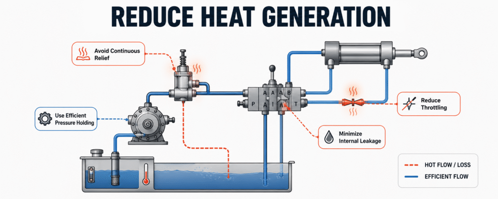
High-temperature hydraulic system design should first improve energy efficiency instead of requiring the cooler to remove every avoidable energy loss.
Hydraulic energy is converted into heat when oil flows through relief valves, throttling valves, restrictive pipes, and worn components.
The design should avoid:
- Continuous operation of the relief valve
- Long periods of high-pressure flow from a fixed-displacement pump
- Pump flow significantly exceeding actuator demand
- Large flow passing through a proportional valve at a small opening
- Continuous pump flow after an actuator reaches the end of its stroke
- Long pressure-holding periods supported only by pump flow
- Undersized valve passages
- Pumps and valves operating far outside their efficient working range
For machines with widely changing flow demand, a variable-displacement pump or load-sensing control may reduce excess flow and pressure losses.
For fixed-displacement pump systems, an unloading circuit should be considered so that the pump does not remain under high pressure during idle periods.
When the system must hold pressure or maintain a load for a long time, possible solutions include:
- Hydraulic accumulators
- Pressure-switch-controlled pump operation
- Low-flow pressure-holding circuits
- Pilot-operated check valves
- Counterbalance or load-holding valves
- Independent mechanical or hydraulic locking circuits
Reducing internal heat generation lowers oil temperature and can also reduce motor power consumption, noise, pump wear, and operating costs.
Optimize Pipes and Reservoir Design
Pipe diameter and layout affect suction resistance, pressure loss, return-line backpressure, and heat generation.
Pipe selection should not be based only on the thread size of the component ports. The internal diameter should be selected according to actual maximum flow, acceptable oil velocity, and allowable pressure drop.
Important design points include:
- Keeping the suction line short and unrestricted
- Avoiding excessive elbows and sharp bends
- Selecting pressure lines for maximum operating flow
- Providing sufficient return-line diameter
- Checking the flow capacity of quick couplings
- Avoiding unnecessarily long hoses
- Matching filter and cooler ratings to actual flow
- Calculating the combined pressure drop of components installed in series
The return line is often underestimated.
If the return filter, cooler, fittings, and pipes create excessive resistance, the pump must generate additional pressure to return oil to the reservoir. This pressure loss is continuously converted into heat.
The reservoir also plays an important role in cooling, air release, contaminant settling, and water separation.
A reservoir for continuous high-temperature operation should have:
- Adequate effective oil volume
- Sufficient external surface area
- Correct suction and return port locations
- Internal baffles
- Controlled return-oil velocity
- Suitable oil residence time
- A clearly defined oil-level range
- Good airflow around the tank
Hot return oil should not flow directly into the pump suction area. A properly positioned baffle increases the oil travel path and provides more time for heat release and air separation.
The reservoir should also be installed away from engines, exhaust pipes, furnaces, and other external heat sources whenever possible.
Design the Cooling System According to Heat Load
A cooler should not be selected only by pump flow or connection size.
The cooling system should be based on:
- Estimated heat generation
- Target operating oil temperature
- Maximum summer ambient temperature
- Continuous operating duration
- Oil flow through the cooler
- Oil-side pressure drop
- Available airflow or cooling-water conditions
- Installation space
- Machine load variation
- Required cooling reserve
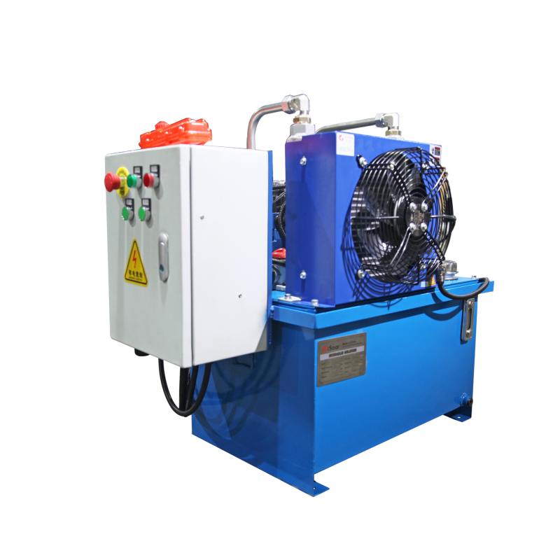
Air-cooled oil coolers are common on mobile equipment and systems without a stable water supply. Their actual performance, however, depends on ambient temperature, fan airflow, fin cleanliness, and installation position.
Hot air discharged from the cooler must be able to leave the enclosure. If the air is drawn back into the cooler, heat recirculation can significantly reduce cooling capacity.
Water-cooled oil coolers are often more suitable for stationary equipment, continuous-duty systems, and high thermal loads. Their performance depends on cooling-water temperature, flow, water quality, scaling, and corrosion control.
A reasonable design margin should be included for higher-than-expected ambient temperatures, increased production cycles, or future system expansion.
However, cooling capacity should not be used to compensate for continuous relief flow, excessive throttling, or severe internal leakage. Heat sources should be reduced before finalizing cooler size.
Select Suitable Hydraulic Oil and Temperature-Resistant Components
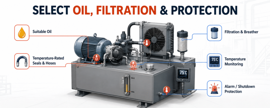
The hydraulic oil must remain within the viscosity range required by the pump and control components throughout the expected temperature range.
Oil selection should consider:
- Minimum startup temperature
- Normal operating oil temperature
- Maximum oil temperature
- Required viscosity grade
- Viscosity index
- Oxidation resistance
- Anti-wear performance
- Air-release performance
- Foam resistance
- Demulsibility
- Compatibility with seal materials
Oil that is too viscous increases suction, filter, and pipe resistance. Oil that becomes too thin increases internal leakage in pumps, valves, cylinders, and motors.
High-temperature hydraulic oil can improve viscosity retention and oxidation resistance, but it cannot correct poor circuit efficiency or inadequate cooling.
Seals, hoses, solenoid coils, sensors, connectors, and electrical components must also be selected for their continuous operating temperature, not only their short-term peak rating.
Seal and hose selection should consider oil temperature, ambient temperature, pressure, pressure pulsation, fluid type, movement speed, and exposure to external heat.
When components cannot be relocated away from an engine or exhaust system, heat shields, insulating sleeves, or revised pipe routing may be required.
Strengthen Contamination Control and Temperature Protection
High temperature accelerates hydraulic oil oxidation and increases the damage caused by air, water, and solid particles.
The system should therefore include:
- Filtration matched to component cleanliness requirements
- Filters with sufficient flow capacity
- Differential pressure indicators or clogging alarms
- A suitable reservoir breather
- Water and condensation control
- Drain and cleaning points
- Filtered new-oil filling
- Oil sampling ports
Systems using proportional valves, servo valves, or other precision components usually require stricter contamination control.
Temperature monitoring should also be included in the original design.
Useful monitoring locations include:
- Reservoir
- Main return line
- Cooler inlet
- Cooler outlet
- Pump outlet
- Pump case drain
- Enclosed equipment compartment
The control system may automatically:
- Start the cooling fan
- Open the cooling-water supply
- Activate a high-temperature warning
- Reduce the operating cycle frequency
- Limit high-load movements
- Stop the machine when the temperature becomes unsafe
Alarm and shutdown temperatures should be based on the limits of the oil, pump, seals, hoses, and electrical components. One universal temperature setting is not suitable for every hydraulic system.
Information Required Before High-Temperature System Design
| Category | Information to Confirm |
|---|---|
| Temperature | Normal and maximum ambient temperature, expected oil temperature, maximum allowable oil temperature |
| Pressure | Working pressure, peak pressure, holding pressure, and holding time |
| Flow | Maximum flow, average flow, and flow required by each movement |
| Duty cycle | Movement sequence, cycle frequency, idle time, and continuous operating time |
| Actuators | Number, load, speed, and operating direction of cylinders or motors |
| Hydraulic fluid | Fluid type, viscosity grade, and any special medium |
| Installation | Space, ventilation, dust, water exposure, and external heat sources |
| Cooling and control | Air or water cooling conditions, sensors, alarms, and shutdown requirements |
Conclusion
The key to high-temperature hydraulic system design is not simply installing a larger cooler or replacing standard components with high-temperature versions.
A reliable design starts with the actual ambient temperature, oil temperature, pressure, flow, duty cycle, and continuous operating time. Unnecessary heat from relief flow, throttling, internal leakage, and pressure loss should be reduced first.
The pump, valves, pipes, reservoir, cooler, oil, seals, hoses, and electrical components must then be selected as one complete thermal system.
With suitable contamination control, temperature monitoring, automatic cooling, and overtemperature protection, the hydraulic system will be better able to maintain stable performance during summer and other high-temperature operating conditions.