A hydraulic pump, valve and cylinder may each meet their individual specifications, but that does not necessarily mean they will work well together. In many hydraulic systems, poor performance comes from component mismatch rather than a defective component.
The cylinder determines how much force and oil flow the machine requires. The pump must provide the necessary flow at the required pressure, while the valves must control that flow without creating excessive pressure loss or restricting actuator movement.
A practical matching sequence is:
Load & Speed → Cylinder → Required Pressure & Flow → Pump → Valves → System Verification
Understanding this relationship helps avoid common problems such as insufficient cylinder force, slow movement, excessive heat and unnecessary energy consumption.
Start Hydraulic System Matching with the Cylinder
When matching hydraulic components, the cylinder is usually the best starting point because it converts hydraulic energy into the actual force and movement required by the machine.
The main cylinder parameters are bore diameter, rod diameter, stroke, working pressure and required movement speed. Bore size determines the piston area and therefore strongly affects both force and oil demand.
The basic cylinder force relationship is:
F = P × A
where F is force, P is pressure and A is effective piston area.
A larger bore produces more force at the same pressure, but it also requires more hydraulic oil for the same movement speed. This means changing cylinder size can affect both pump and valve requirements.
For a single-rod cylinder, retraction should also be checked separately because the rod reduces the effective area on the rod side. Retraction force is therefore lower than extension force, while retraction speed is normally higher when the same flow is supplied.
Match Hydraulic Pump Pressure to Cylinder Force
Once the cylinder bore and required machine force are known, the approximate operating pressure can be calculated.
For example, an 80 mm bore cylinder has a piston area of approximately 5,027 mm². At 160 bar, its theoretical extension force is approximately:
F = P × A ≈ 80 kN
Actual cylinder output will be somewhat lower because of mechanical friction and hydraulic pressure losses.
The pump therefore needs to operate at a pressure sufficient to overcome the load and circuit losses. However, this does not mean that selecting a much higher-pressure pump automatically improves system performance.
Cylinder, pump, valves, hoses, fittings and manifolds all have pressure ratings. The hydraulic system working pressure and relief-valve setting must remain within the allowable ratings of the complete circuit.
A common matching mistake is trying to solve insufficient cylinder force simply by increasing system pressure. If the cylinder is too small for the load, selecting the correct cylinder size may be a better solution than continuously increasing pressure.
Match Hydraulic Pump Flow to Cylinder Speed
Pressure determines whether the cylinder can overcome the load, while flow determines how quickly it moves.
Cylinder speed can be estimated from:
v = Q ÷ A
where v is cylinder speed, Q is flow and A is effective piston area.
Suppose an 80 mm bore cylinder needs an extension speed of 0.08 m/s. The required theoretical flow is approximately:
24 L/min
The pump must therefore provide approximately this amount of usable flow if the cylinder is expected to reach the target speed.
Pump displacement, rotational speed and volumetric efficiency determine the available flow:
Pump Flow ≈ Displacement × RPM × Volumetric Efficiency
The actual pump should be selected with system losses and real operating conditions in mind rather than matching the theoretical cylinder demand exactly.
If several cylinders or hydraulic motors need to operate simultaneously, their flow demands must also be considered together. A pump sized for only one actuator may cause all functions to slow down when several functions operate at the same time.
Match Hydraulic Valves to Pump Flow
Once pump flow has been established, the valves must be able to handle that flow efficiently.
A valve that is too small creates restriction. As oil passes through a restrictive flow path, pressure drops across the valve. This reduces the pressure available to the actuator and converts hydraulic power into heat.
For this reason, valve selection should consider rated flow and expected pressure drop, not only port size.
For example, if the cylinder requires approximately 24 L/min, the directional valve should have a continuous flow capacity comfortably above the actual operating flow under the expected pressure conditions. Manufacturer flow-pressure curves should be checked where available.
The same principle applies to flow controls, check valves, counterbalance valves and manifold passages. One undersized component can restrict the performance of the entire hydraulic system.
Match Hydraulic Valve Functions to Cylinder Behavior
Flow capacity is only one part of valve selection. The valve configuration must also match how the cylinder is expected to operate.
A double-acting cylinder typically requires a directional valve that can supply and return oil from both cylinder chambers. A single-acting cylinder may use a different valve arrangement because hydraulic pressure normally moves the cylinder in only one direction.
Load conditions also matter. A vertically loaded cylinder may require a pilot-operated check valve or counterbalance valve to prevent uncontrolled movement. A cylinder that needs adjustable speed may require flow control, while applications requiring continuously variable speed or position may use proportional control.
Therefore, valve matching should answer two questions:
Can the valve handle the required pressure and flow?
and
Does the valve provide the control function required by the actuator?
Both need to be correct for the hydraulic system to operate properly.
Check Pressure Loss Through the Complete Hydraulic Circuit
Pump pressure is not the same as the pressure that finally reaches the cylinder.
Oil may pass through directional valves, flow controls, hoses, fittings, filters and manifolds before reaching the actuator. Each component creates some pressure loss.
For example, if the pump outlet pressure is 160 bar but the circuit loses 10 bar before the cylinder, only approximately 150 bar is available at the actuator under those operating conditions.
Pressure loss also generates heat. The approximate hydraulic power lost through a restriction can be estimated from:
Power Loss (kW) = Pressure Drop (bar) × Flow (L/min) ÷ 600
This is why oversizing the pump and then heavily throttling the flow at a valve is usually inefficient. The system may still achieve the required cylinder speed, but unnecessary pump flow is being converted into heat.
Good hydraulic component matching aims to provide the required pressure and flow without creating excessive restriction.
Example of Matching a Pump, Valve and Cylinder
Consider a simple hydraulic system with the following cylinder requirement:
| Parameter | Example |
|---|---|
| Cylinder bore | 80 mm |
| Rod diameter | 40 mm |
| Required extension speed | 0.08 m/s |
| Working pressure | 160 bar |
| Extension flow requirement | Approx. 24 L/min |
| Theoretical extension force | Approx. 80 kN |
The cylinder requirement tells us that the pump must provide approximately 24 L/min of usable flow at the required operating pressure.
The pump should therefore be selected according to the target flow, operating pressure, pump speed and expected efficiency. The directional valve and other control valves should have pressure ratings suitable for the system and flow capacities comfortably above the actual working flow.
The complete matching logic is:
80 mm Cylinder
→ requires approximately 160 bar for the target force
→ requires approximately 24 L/min for the target speed
→ determines the required Pump Pressure & Flow
→ determines the required Valve Pressure & Flow Capacity
→ followed by verification of Pressure Loss, Heat and Control Behavior
This is more reliable than selecting the pump, valve and cylinder independently.
Common Hydraulic Component Matching Mistakes
One common mistake is matching components only by maximum pressure. Two components may both be rated for 250 bar, but that does not mean their flow capacities or control characteristics are compatible.
Another mistake is selecting valves according to connection size alone. Two valves with the same port size can have very different internal flow capacities and pressure drops.
Oversized pumps can also cause problems. More flow is not always better. If the cylinder does not need the additional flow, it may need to be throttled or returned to the reservoir, increasing energy consumption and heat generation.
The key is to match cylinder force and speed requirements with pump pressure and flow, then ensure the valves can control that flow efficiently and safely.
Conclusion: Match the Hydraulic System as One System
Hydraulic pumps, valves and cylinders should never be selected as completely independent components.
Start with the load and required movement. Use these requirements to determine the cylinder size, operating pressure and required flow. Then select a pump capable of supplying that pressure and flow, followed by valves that can handle the required capacity and provide the correct control functions.
The fundamental matching relationship is:
Cylinder Force → Pressure
Cylinder Speed → Flow
Pump → Supplies Pressure & Flow
Valves → Control Pressure, Flow and Direction
When these components are correctly matched, the hydraulic system can achieve the required force, speed and control while reducing unnecessary pressure loss, heat generation and component oversizing.
Need Help Matching Hydraulic System Components?
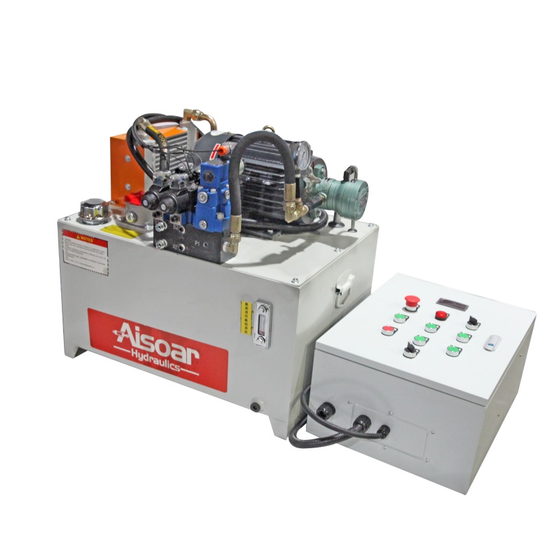
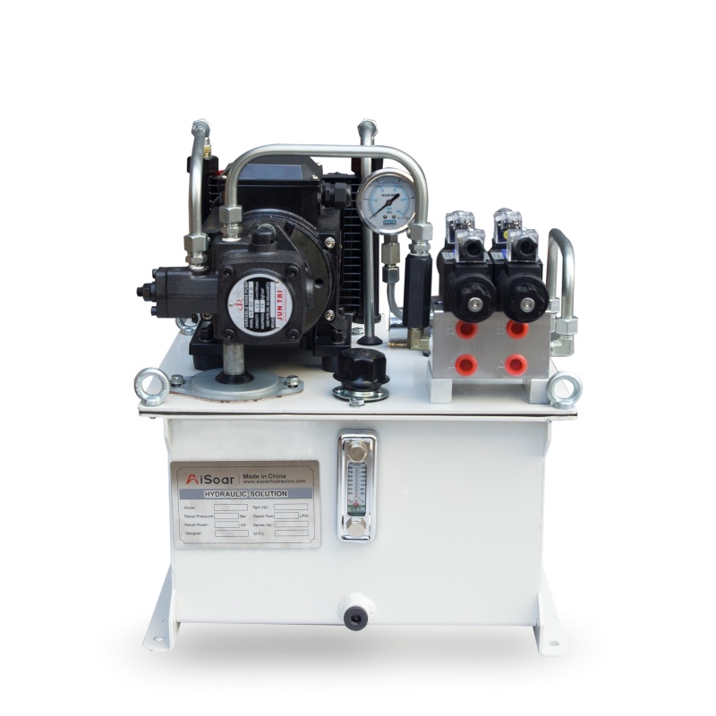
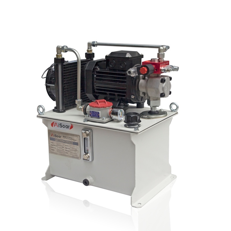
AISOAR provides customized hydraulic power units and hydraulic system solutions according to cylinder specifications, required pressure, flow, duty cycle and control requirements.
For an OEM hydraulic system project, providing the cylinder bore, rod diameter, stroke, required force, movement speed, working cycle and available power supply can help our engineering team evaluate an appropriate pump, valve and hydraulic system configuration.