If you work with fluid power systems, knowing how to read a hydraulic schematic is essential for troubleshooting, maintenance, and system design. A hydraulic drawing may look complex at first, but once you understand hydraulic symbols and flow logic, it becomes much easier to follow.
In this guide, we’ll break down the most common hydraulic schematic symbols, explain how to trace oil flow, and show how to interpret a full hydraulic power unit (HPU) circuit.
Common groups of fluids circuit elements
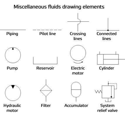
A typical hydraulic circuit includes several essential components that work together to deliver stable and efficient fluid power. The reservoir (tank), usually shown as an open-top rectangle, stores and cools hydraulic fluid. A hydraulic pump (circle with an outward-pointing filled triangle) converts mechanical energy into hydraulic flow, while a hydraulic motor (inward-pointing triangle) converts that flow back into rotary motion. Linear motion is produced by a hydraulic cylinder (actuator), represented as a rectangle with a piston rod. System logic is controlled by the directional control valve (DCV), drawn as adjacent boxes with arrows and blocked ports to indicate different spool positions and flow paths. To protect the circuit, a pressure relief valve limits maximum pressure by diverting excess fluid to tank. A check valve ensures one-way flow, and a flow control valve regulates flow rate to control actuator speed. Fluid cleanliness is maintained by a hydraulic filter, and a pressure gauge provides real-time pressure monitoring for safer operation and easier diagnostics. Together, these hydraulic schematic symbols form the foundation of hydraulic system design, troubleshooting, and performance optimization.
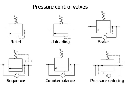
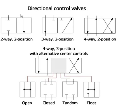
In hydraulic system schematics, control valves are the key components that define circuit logic, motion control, and overall system stability. The three main categories are directional control valves, pressure control valves, and flow control valves. Directional control valves route hydraulic fluid to start, stop, and reverse actuators such as hydraulic cylinders and motors. Pressure control valves regulate or limit system pressure; common types include relief valves, reducing valves, sequence valves, and counterbalance valves, which provide overload protection and staged operation. Flow control valves adjust flow rate by changing the effective orifice area, helping control actuator speed and cycle consistency.
Analysis of Specific Fluid Circuit Components
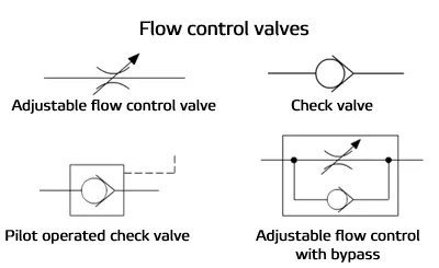
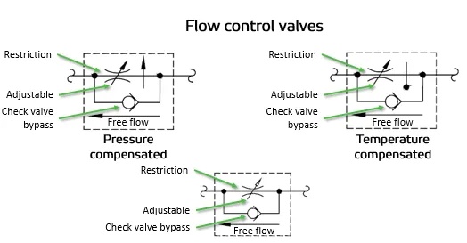
Flow control valves
Flow control valves are used to regulate oil flow in one direction and allow free flow in the opposite direction. “Meter-in” control means the valve regulates fluid entering the actuator, while “meter-out” control means the valve regulates fluid leaving the actuator. This allows actuator speed to be adjusted for different load conditions. Some flow control valves are available with pressure and/or temperature compensation to maintain more consistent flow under changing system conditions.
| Air Bleed Valve | Air bleed valves automatically remove trapped air from pressurized hydraulic systems. By reducing air pockets, they improve system stability and motion accuracy. | 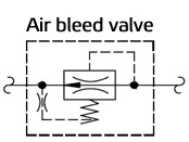 |
| Pilot-Operated Check Valve (Pilot-to-Open) |
A pilot-to-open check valve allows flow in one direction and blocks reverse flow when the pilot line is not pressurized.When pilot pressure is applied, the valve opens and permits flow in both directions. | 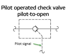 |
| Pilot-Operated Check Valve (Pilot-to-Close) |
In normal condition (no pilot pressure), this valve behaves like a standard check valve: one-way flow allowed, reverse flow blocked.When pilot pressure is applied, the valve closes and can block flow in both directions. | 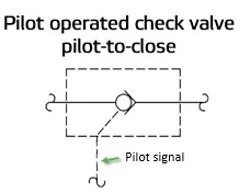 |
| Shut-Off Valve | Shut-off valves isolate one section of a fluid circuit from another. They are commonly used for maintenance, safety lockout, and subsystem separation. | 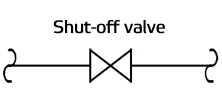 |
| Level Switch | A level switch monitors fluid level in a reservoir. A typical use is to detect low oil level and trigger an alarm or machine protection logic. | 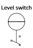 |
| Temperature Switch | Temperature switches detect when fluid reaches a defined temperature limit. They are often used to signal overheating conditions in the hydraulic tank. | 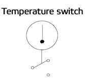 |
| Pressure Switch | Pressure switches detect pressure rise or drop at a preset threshold. Depending on model, setpoints may be fixed or adjustable. | 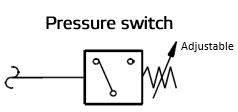 |
| Pressure Reducing Valve | Pressure reducing valves maintain a lower pressure in a branch circuit than the main system pressure. They protect downstream components and improve control in specific functions. | 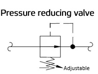 |
| Pressure Relief Valve | Pressure relief valves limit maximum pressure in all or part of a hydraulic system. They are critical safety devices that prevent overpressure damage. | 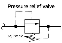 |
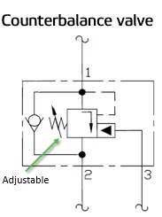
| Counterbalance Valve | Counterbalance valves control overrunning loads and hold suspended loads in position. They help prevent uncontrolled movement if flow is interrupted. Note: These valves are typically factory-set and should only be adjusted by qualified personnel. |
 |
| Flow Fuse | A flow fuse is normally open and closes when flow/pressure differential exceeds its design limit. It can typically be reset by reversing flow direction. Installed near actuators, it helps limit speed in case of hose or line failure | 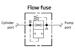 |
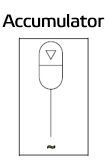
| Accumulator | Accumulators store hydraulic energy and absorb pressure shocks. They can stabilize pressure, provide emergency energy, and reduce pump cycling.
Warning: Always release stored hydraulic pressure before servicing |
 |
| Directional Control Valve | Directional control valves route fluid to the required lines for each machine function. They may be manually, hydraulically, pneumatically, or electrically actuated. | 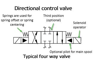 |
| Hydraulic Pump | Hydraulic pumps move fluid from the reservoir to the working circuit. Some pump designs include pressure compensation, flow compensation, or load-sensing control. | 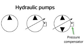 |
| Filter | Filters remove contamination from hydraulic fluid. Clean fluid extends component life and improves system reliability. | 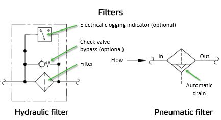 |
| Strainer | Strainers remove larger particles, typically at pump inlets or supply lines. Some models include bypass/check features. | 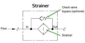 |
| Water Modulating Valve | Water modulating valves regulate cooling water through a heat exchanger to control hydraulic oil temperature automatically. | 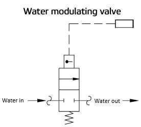 |
| Heat Exchanger (Cooler) | Hydraulic coolers remove heat from circulating oil. Common options include water-to-oil and air-to-oil designs. | 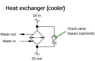 |
| Heat Exchanger (Heater) | Hydraulic heaters raise oil temperature for cold-start performance and viscosity control. | 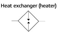 |
| Hydraulic Cylinder | Cylinders convert hydraulic energy into linear mechanical force and motion. | 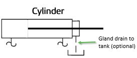 |
| Hydraulic Motor | Hydraulic motors convert fluid power into rotary mechanical output. | 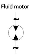 |
| Quick Disconnect Coupling | Quick disconnects allow fast connection and separation of hydraulic lines between machine sections or attachments. | 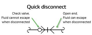 |
| Proportional / Servo Valve | Proportional (or servo) valves are electrically controlled valves that modulate pressure and/or flow according to an input signal for precise motion control. | 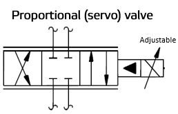 |
| Muffler | Mufflers reduce exhaust air noise in pneumatic systems. | 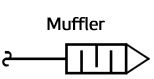 |
| Air Blow | Air blow points are used for directed compressed-air discharge, often for cleaning, drying, or part ejection functions. | 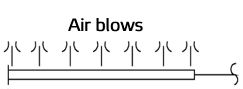 |
Conclusion
Reading hydraulic power unit schematics becomes much easier once you understand the core symbols and the function of each component. From directional valves, relief valves, and flow controls to accumulators, filters, coolers, cylinders, and motors, every symbol represents a specific role in controlling pressure, flow, temperature, and motion. By learning how these elements interact in a circuit, technicians and engineers can diagnose faults faster, improve maintenance efficiency, and optimize system performance. In short, a solid understanding of hydraulic symbols is the foundation for safer operation, reduced downtime, and better hydraulic system reliability.