Understanding hydraulic formulas is essential for system design, component selection, and troubleshooting. This article provides a structured collection of commonly used equations, covering Basic Hydraulic Principles, Hydraulic Formulas for Cylinders and Actuators, Hydraulic Formulas for Motors and Pumps, and Hydraulic Formulas in Hydraulic Systems. Each formula is grouped by application and paired with variable definitions to help engineers and technicians find what they need quickly. Whether you are calculating cylinder force, pump flow, motor torque, or line pressure loss, this reference is designed to improve calculation speed and accuracy.
Basic Hydraulic Principles
| Category | Formula | Variables (Symbol: Meaning) |
| Pressure Definition | p = F/A | (p): pressure; (F): force; (A): effective area |
| Hydraulic Force | F=pA | (F): hydraulic force; (p): pressure; (A): effective area |
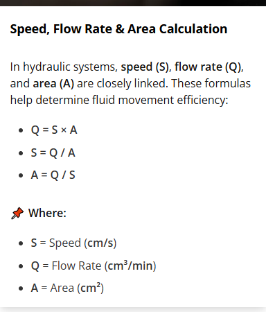
| Flow | Q=Av | (Q): volumetric flow rate; (A): cross-sectional area; (v): fluid velocity |
| Pipe Velocity | v=4Q/πD² | (v): average velocity; (Q): flow rate; (D): pipe inner diameter |
| Hydraulic Power | P=pQ | (P): hydraulic power; (p): pressure; (Q): flow rate |
| Reynolds Number | Re=ρvD/μ | (Re): Reynolds number; (ρ): fluid density; (v): velocity; (D): diameter; (μ): dynamic viscosity |
Hydraulic Formulas for Cylinders and Actuators
Hydraulic cylinders are essential elements of hydraulic systems, acting as linear actuators that produce force to lift, lower, or move heavy loads. Much like a machine’s muscles, they use hydraulic fluid to deliver strong mechanical motion. Below are the key hydraulic formulas for calculating critical cylinder parameters.
| Category | Formula | Variables (Symbol: Meaning) |
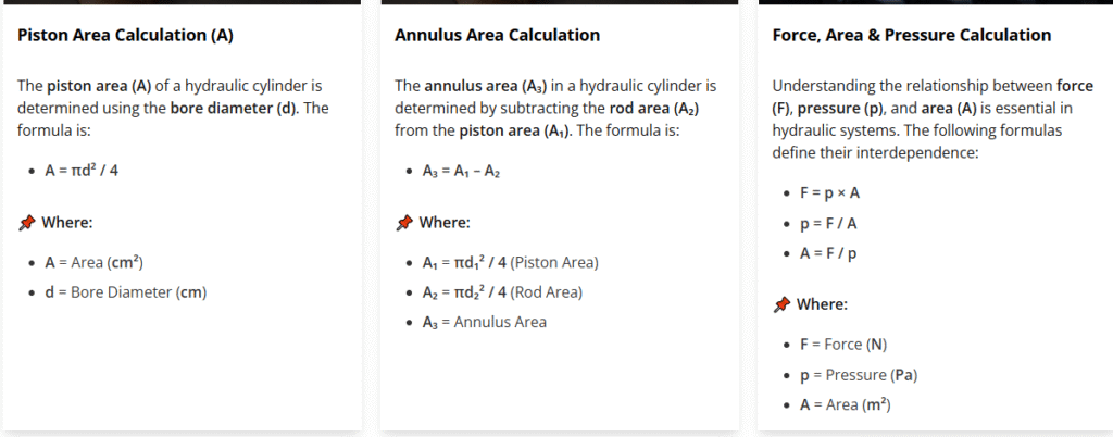
| Piston Area | Ap=πD²/4 | (A): piston area; (d): piston diameter |
| Rod Area | Ar=πD²/4 | (Ar): rod area; (d): rod diameter |
| Cylinder Extension Force | F₁=pA | (F): extension force; (p): pressure; (A): piston area |
| Cylinder Retraction Force | F₂=p(Ap-Ar) | (Fret): retraction force; (p): pressure; (Ap): piston area; (Ar): rod area |
| Extension Speed | v₁=Q/Ap | (v₁): extension speed; (Q): inlet flow rate; (Ap): piston area |
| Retraction Speed | v₂=Q/(Ap-Ar) | (v₂): retraction speed; (Q): inlet flow rate; (Ap): piston area; (Ar): rod area |
| Cylinder Output Power | P=Fv | (Pout): output power; (F): actuator force; (v): linear speed |
Hydraulic Formulas for Motors and Pumps
Although hydraulic pumps and motors look alike in structure, their roles are different. A hydraulic pump is driven by an external power input—such as an electric motor or an engine—to create fluid flow in the system. A hydraulic motor, however, does the opposite: it converts hydraulic flow and pressure into rotational mechanical output.
The following are core hydraulic equations used to determine key performance values for both pumps and motors.
| Category | Formula | Variables (Symbol: Meaning) |
| Theoretical Pump Flow | Qt=Vd·n | (Qt): theoretical flow rate; (Vd): displacement per revolution; (n): rotational speed |
| Actual Pump Flow | Q=Vd·n·ηv | (Q): actual flow rate; (Vd): displacement; (n): speed; (ηv): volumetric efficiency |
| Pump Input Power | P(in)=pQ/η₁ | (P{in}): pump input power; (p): pressure rise; (Q): flow rate; (η₁): overall efficiency |
| Hydraulic Motor Torque | T=(Δp·Vd·η₂)/(2π) | (T): output torque; (Δp): pressure differential; (Vd): displacement; (η₂): mechanical efficiency |
| Hydraulic Motor Speed | n=Q·ηv/Vd | (n): motor speed; (Q): inlet flow rate; (ηv): volumetric efficiency; (Vd): displacement |
| Motor Output Power | P{out}=2π·n·T | (P{out}): motor output power; (n): rotational speed; (T): torque |
| Overall Efficiency | ηo=ηv·ηm | (ηo): overall efficiency; (ηv): volumetric efficiency; (ηm): mechanical efficiency |
Hydraulic Formulas in Hydraulic Systems
(Piping, Valves, Losses)
Hydraulic piping, valves, and system losses play a critical role in overall hydraulic efficiency and performance. Pressure drops caused by line length, fittings, valve restrictions, and flow velocity can significantly affect actuator speed, output force, and energy consumption. To design stable and efficient hydraulic circuits, engineers must accurately evaluate these system-level factors. Below are essential hydraulic formulas for calculating piping flow characteristics, valve-related pressure losses, and total system losses.
| Category | Formula | Variables (Symbol: Meaning) |
| Darcy–Weisbach Major Loss | Δpf=f·(L/D)·(ρv²/2) | (Δpf): major pressure loss; (f): friction factor; (L): pipe length; (D): diameter; (ρo): density; (v): velocity |
| Local Loss (Valve/Fitting) | Δpl=K(ρv²/2) | (Δpl): local pressure loss; (K): local loss coefficient; (ρ): density; (v): velocity |
| Total Line Loss | Δptot=Δpf+ΣΔpl | (Δp{tot}): total pressure loss; (Δpf): major loss; (ΣΔpl): sum of local losses |
| Orifice/Valve Flow | Q=CdA√(2Δp/ρ) | (Q): flow rate; (Cd): discharge coefficient; (A): orifice area; (Δp): pressure drop; (ρ): density |
| Pressure–Head Relation | Δp=ρgh | (Δp): pressure difference; (ρ): density; (g): gravity acceleration; (h): head difference |
Summary
In summary, hydraulic formulas and calculations are the foundation of reliable system design, performance optimization, and troubleshooting. Whether you are sizing pumps and motors, calculating cylinder force, or evaluating piping and valve losses, accurate calculations help ensure efficiency, safety, and long-term equipment stability. By mastering these core equations, engineers and technicians can make better design decisions, reduce energy waste, and improve overall hydraulic system performance.