Hydraulic valves control pressure, flow and direction throughout a hydraulic system. If a valve does not open at the correct pressure, shifts incompletely, leaks internally or restricts flow excessively, the entire hydraulic system can behave incorrectly even when the pump and actuator are functioning normally.
A hydraulic valve test bench is used to evaluate these functions under controlled pressure and flow conditions. Depending on the valve type, testing may include opening pressure, pressure regulation, switching performance, flow characteristics, pressure drop and internal or external leakage.
For valve manufacturers, repair workshops and hydraulic service facilities, a dedicated test bench provides a repeatable way to verify whether a valve performs according to its required specifications before it is installed in a machine.
What Is a Hydraulic Valve Test Bench?
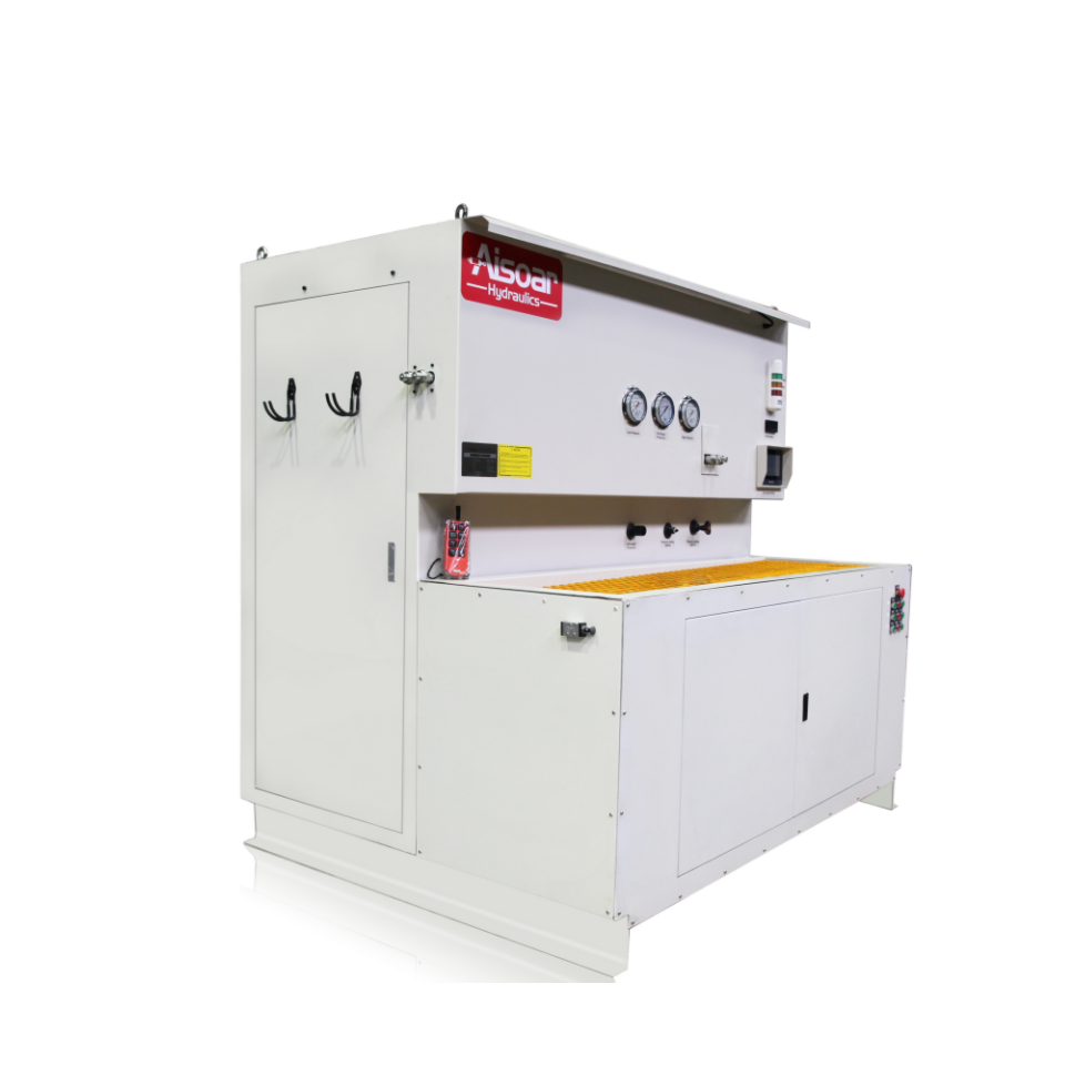
A hydraulic valve test bench is a controlled hydraulic testing system used to supply pressure and flow to a valve while measuring how the valve responds.
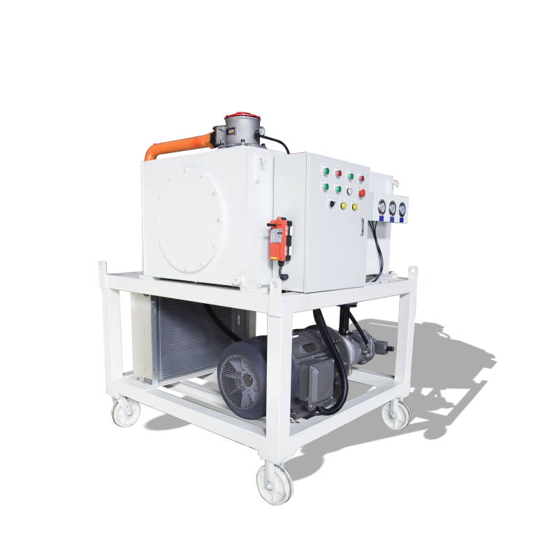
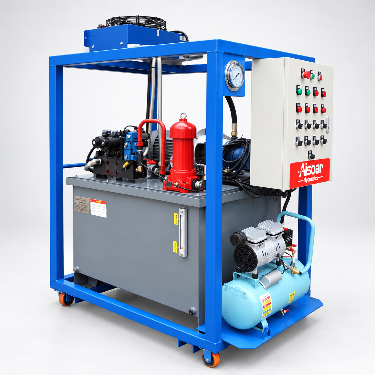
A typical system includes a hydraulic power source, reservoir, filtration, pressure-control circuit, flow-control components, sensors, test connections and a control interface. Depending on the testing requirement, the bench may also include adjustable load simulation, leakage measurement, automatic pressure control and data acquisition.
The exact configuration depends heavily on the valves being tested. A relief valve requires a different test sequence from a directional valve, while a proportional valve may require electrical command signals and more detailed flow-response measurement.
The purpose of the test bench is therefore not simply to apply pressure. It is to reproduce the conditions needed to evaluate the valve’s actual hydraulic function.
What Types of Hydraulic Valves Can Be Tested?
A valve test bench can be configured for many common hydraulic valve types, but the required test circuit should match the valve’s working principle.
Pressure Relief Valves
A relief valve limits maximum hydraulic system pressure by opening when pressure reaches a defined setting.Testing typically focuses on opening pressure, pressure stability, reseating behavior and leakage. The bench gradually increases inlet pressure while monitoring when the valve begins to pass flow.This helps determine whether the valve opens at the correct pressure and whether its behavior remains stable as flow changes.
Directional Control Valves
Directional valves control which hydraulic path is connected to the pump, actuator or tank.Testing may include spool or solenoid switching, pressure drop through different flow paths, internal leakage and correct port connection in each operating position.For electrically operated valves, the test system may also verify coil actuation and switching response.
Pressure Reducing Valves
A pressure reducing valve maintains a lower controlled pressure in one branch of the hydraulic circuit.The test bench can supply varying inlet pressure and flow while monitoring whether the outlet pressure remains close to the required setting.Pressure stability is particularly important because an unstable reducing valve may cause downstream actuators or components to operate inconsistently.
Flow Control Valves
Flow control valves regulate the amount of oil passing through a hydraulic circuit and therefore influence actuator speed.Testing can evaluate the relationship between valve adjustment and actual flow, as well as changes in flow when inlet pressure or load conditions vary.Pressure-compensated flow controls may require additional testing to confirm whether flow remains sufficiently stable as pressure changes.
Check Valves
A check valve allows flow in one direction while restricting reverse flow.Common tests include cracking pressure, forward pressure drop and reverse leakage.For pilot-operated check valves, pilot release pressure and load-holding behavior may also need to be evaluated.
Valve Blocks and Hydraulic Manifolds
A hydraulic manifold may combine several valve functions in one assembly. Testing therefore needs to verify not only individual components but also how the complete internal circuit behaves.
Functional sequence, pressure control, leakage, cross-port interaction and flow capacity may all need to be checked according to the manifold design.
What Tests Can a Hydraulic Valve Test Bench Perform?
Although the exact test items depend on the valve type, several test functions are common across hydraulic valve testing.
| Test Item | What It Evaluates |
|---|---|
| Opening / cracking pressure | Pressure at which the valve begins operating |
| Pressure regulation | Ability to maintain the required pressure |
| Flow test | Amount of oil passing through the valve |
| Pressure drop | Resistance created by the valve at a given flow |
| Internal leakage | Oil bypassing internally when the valve should seal |
| External leakage | Oil escaping from the body, ports or seals |
| Switching function | Correct directional operation |
| Reseating performance | Whether a pressure valve closes correctly after activation |
A repair workshop may use only the tests necessary to confirm that a repaired valve functions correctly. A valve manufacturer may require more standardized test sequences and defined acceptance limits for every production unit.
For automated production testing, pressure, flow and leakage values can be recorded and compared with preset PASS / FAIL limits.
How Does a Hydraulic Valve Test Bench Work?
The basic testing principle is to supply controlled hydraulic pressure and flow to the valve, create the required operating condition and measure the valve response.
The process generally begins by connecting the test valve to the correct ports and verifying that all hoses, adapters and fixtures have suitable pressure ratings. The hydraulic system is then operated at relatively low pressure to confirm correct connections and remove trapped air.
After the initial check, pressure and flow are increased according to the required test procedure.
For a relief valve, for example, the test bench may gradually increase pressure while measuring when the valve starts opening. Once the opening point is identified, the system can continue to measure pressure behavior at different flow rates.
For a directional valve, the bench may activate different spool positions and measure pressure and flow at the corresponding ports. Leakage can then be checked while the valve is in neutral or another specified position.
A basic valve-testing sequence can therefore be summarized as:
Valve Identification → Connection → Low-Pressure Check → Apply Test Pressure & Flow → Operate Valve → Measure Performance → Leakage Check → Record Result
The exact order should always follow the valve specification and required test procedure.
What Parameters Matter When Selecting a Hydraulic Valve Test Bench?
Maximum pressure is important, but it is not the only parameter that determines whether a test bench can test a particular valve.
Flow capacity is equally important because pressure drop and valve behavior may change significantly as flow increases. A valve designed for 100 L/min cannot be fully evaluated on a test system that can only deliver a small fraction of that flow.
The test bench should also consider the number and size of valve ports, connection types, required test oil, temperature range and leakage measurement range.
For proportional or electrically controlled valves, the electrical control system may need to supply specific voltage or current signals. Data acquisition may also need a higher sampling rate when response characteristics are being evaluated.
Measurement accuracy should be selected according to the test purpose. Basic repair verification may require a different accuracy level from development testing or standardized production quality control.
Manual, Semi-Automatic or PLC-Controlled Valve Testing?
The required automation level depends on test volume and how repeatable the procedure needs to be.
A manual hydraulic valve test bench allows the operator to adjust pressure, flow and valve controls directly. This can be suitable for repair workshops where many different valve types are tested and procedures vary from one job to another.
A semi-automatic system can automate selected functions such as pressure ramping, data recording or leakage measurement while maintaining operator flexibility.
For production testing, PLC-controlled operation can provide more consistent procedures. Test recipes can define pressure, flow, operating steps, holding time and acceptance criteria for each valve model.
Automatic data recording can also link results to a serial number, job number or batch, helping manufacturers improve traceability and quality control.
The best automation level is therefore determined by the test workflow rather than by choosing the most complex system available.
Why Hydraulic Valve Testing Matters?
A hydraulic valve can appear normal externally while still causing serious system problems.
A relief valve that opens too early can prevent a machine from developing sufficient pressure. A directional valve with excessive internal leakage may cause actuator drift or slow movement. A restricted flow-control valve can increase pressure loss and heat, while a damaged check valve may allow a suspended load to move unexpectedly.
Testing the valve separately helps determine whether the problem originates in the valve or elsewhere in the hydraulic system.
For repaired components, this reduces the risk of reinstalling a faulty valve. For production environments, standardized testing helps ensure that every valve or manifold meets the same defined performance requirements before shipment.
Conclusion
A hydraulic valve test bench provides controlled pressure and flow conditions for evaluating the performance of relief valves, directional valves, pressure-reducing valves, flow-control valves, check valves and hydraulic manifolds.
The main testing logic is:
Supply Pressure & Flow → Operate the Valve → Measure Response → Check Leakage → Compare with Acceptance Criteria
The correct test bench should be selected according to valve type, maximum pressure, flow range, leakage measurement, control method and required level of automation.
When these parameters are matched correctly, valve testing can improve repair verification, production consistency and overall hydraulic system reliability.
Need a Hydraulic Valve Test Bench?
AISOAR provides customized hydraulic test bench solutions for hydraulic valve manufacturers, repair workshops and industrial service facilities.
Test systems can be configured according to valve type, working pressure, flow range, number of test ports, leakage measurement, electrical control requirements, automation level and data-recording needs.
For a new valve test bench project, providing the valve drawings, pressure and flow range, valve type and required test procedure can help our engineering team evaluate a suitable test configuration.