Cleaning the cooler, replacing the hydraulic oil, or adjusting the relief valve may solve an immediate overheating problem, but these actions do not guarantee that the system will remain stable.
If routine maintenance is neglected, the cooler can become blocked again, the oil may be contaminated, and internal leakage in pumps and valves can continue to increase. As these conditions develop, the system gradually loses efficiency and the oil temperature begins to rise again.
Summer maintenance should therefore not begin only after a high-temperature alarm occurs. A more effective approach is to record operating temperatures, compare hot and cold performance, and identify early changes in cooling capacity, oil condition, and component efficiency.
The following checks can help prevent repeated overheating during hot weather and continuous-duty operation.
Record Oil Temperature and Hot-Running Performance
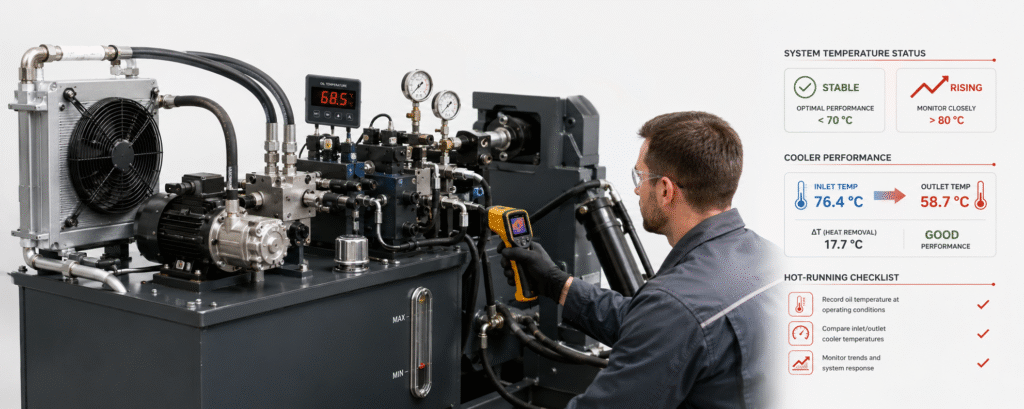
Oil temperature is one of the most useful indicators of hydraulic system condition.
Temperature records are most valuable when measurements are taken under similar loads, cycle times, and ambient conditions. Recommended data includes:
- Ambient temperature
- Oil temperature at startup
- Stabilized oil temperature after continuous operation
- Cooler or fan startup time
- Cooler inlet and outlet temperatures
- Complete machine cycle time
- Time required for a high-temperature alarm to occur
Under normal conditions, the oil temperature rises after startup and eventually stabilizes when system heat generation becomes equal to heat rejection.
If the stabilized temperature becomes higher under the same operating conditions, or if the high-temperature alarm occurs earlier than before, the system may be generating more heat or rejecting less heat.
Cold and hot operating performance should also be compared. Record system pressure, flow, actuator speed, and complete cycle time shortly after startup and again after the oil reaches its normal operating temperature.
If the machine operates normally when cold but becomes slower after running for some time, possible causes include reduced oil viscosity, declining pump efficiency, or increased internal leakage in control valves and actuators.
A trend is often more useful than a single temperature reading. A system that normally stabilizes at 65°C but gradually begins stabilizing at 72°C is showing a meaningful change, even if the alarm has not yet been triggered.
Check Hydraulic Oil Level and Condition
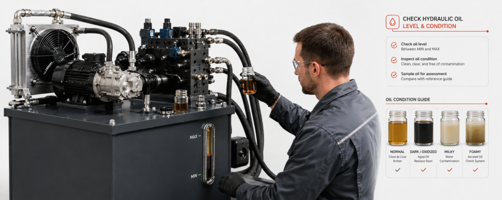
A low oil level reduces the total quantity of oil available to absorb and release heat. It can also allow air to enter the pump inlet, resulting in foaming, noise, pressure fluctuation, and unstable actuator movement.
Oil level should be checked with the machine in the condition specified by the manufacturer. This may require all cylinders to be fully retracted or the equipment to be parked in a defined position.
If the oil level repeatedly falls, do not simply continue topping up the reservoir. Inspect hoses, fittings, valve manifolds, cylinders, motors, and other components for external leakage.
The condition of the oil should also be checked regularly. Warning signs include:
- Noticeably darker oil
- Burnt or unusually sharp odor
- Cloudy or milky appearance
- Persistent foam in the reservoir
- Sludge or deposits
- Metal particles
- Rubber or seal fragments
Dark oil may indicate oxidation caused by prolonged high temperature. Milky or cloudy oil usually suggests water contamination or emulsification. Persistent foam may be related to a low oil level, a leaking suction line, unsuitable return-line design, or air being drawn into the system.
For continuously operating or critical equipment, oil condition should not be evaluated only by color or service hours. Periodic oil analysis can provide information about viscosity, cleanliness level, water content, oxidation, and wear particles.
Oil should be replaced according to its actual condition and the maintenance requirements of the system. Replacing oil without identifying the cause of contamination may only provide temporary improvement.
Maintain Filters, Breathers, and the Reservoir
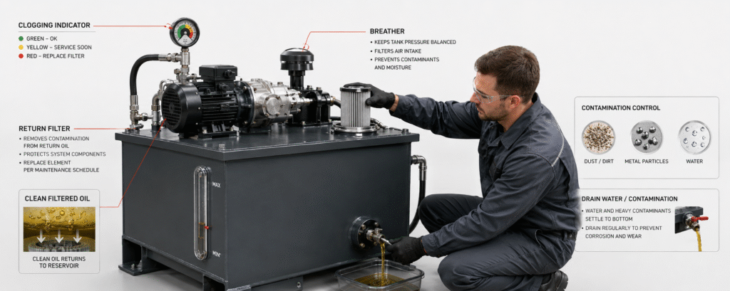
A blocked filter increases pressure loss in the suction, pressure, or return circuit. This additional pressure loss consumes hydraulic power and converts it into heat.
During maintenance, check:
- Filter clogging indicators
- Pressure differential across the filter
- Filter replacement records
- Bypass valve condition
- The type of contamination found in the element
The material collected in a used filter can provide useful diagnostic information. A large quantity of metal particles may indicate abnormal wear in the pump, motor, control valves, or other moving components.
If a new filter becomes blocked again within a short period, the system probably has an active contamination source. Repeated filter replacement alone will not solve the underlying problem.
The reservoir breather should also be inspected, cleaned, or replaced as required. A blocked breather can interfere with pressure balance inside the reservoir, while a damaged or unsuitable breather may allow dust and humid air to enter.
In environments with high humidity or large temperature changes between day and night, condensation may collect at the bottom of the reservoir. Water should be drained in accordance with the maintenance procedure, and sludge or settled contamination should be removed.
New oil should preferably be added through a filtration unit. Oil can collect particles during storage, transportation, and transfer, even when it appears clean in the container.
The reservoir should also be inspected internally when maintenance intervals permit. Check for paint failure, corrosion, accumulated sludge, damaged baffles, and return-line arrangements that may cause excessive turbulence or air entrainment.
Inspect the Cooling System
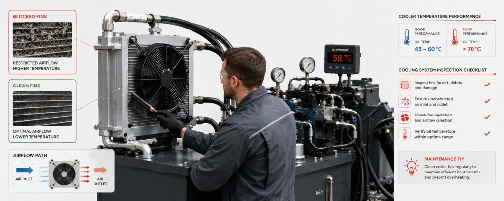
Reduced cooler performance is one of the most common reasons why a hydraulic system overheats again during summer.
For an air-cooled oil cooler, check:
- Dust, oil, leaves, or debris blocking the fins
- Bent or damaged cooling fins
- Fan rotation direction
- Fan speed and electrical condition
- Temperature-switch operation
- Air inlet and outlet restrictions
- Recirculation of hot discharge air
When cleaning the cooler, avoid directing excessively high-pressure water or compressed air at the fins. Thin fins can bend easily, reducing the effective airflow and lowering heat-transfer performance.
The fan should rotate in the correct direction and move air through the cooler as intended. A fan may appear to be operating while still providing insufficient airflow because of incorrect rotation, low motor speed, damaged blades, or restricted ventilation.
For a water-cooled heat exchanger, inspect cooling-water temperature, flow rate, control valves, filters, and internal scale buildup.
A heat exchanger may be mechanically undamaged but still unable to remove enough heat if the cooling water is too warm, the flow is restricted, or scale has reduced the effective heat-transfer area.
Before and after maintenance, compare the cooler inlet and outlet oil temperatures together with the final stabilized reservoir temperature. This helps determine whether cleaning or repair has actually improved cooling performance.
A larger temperature difference across the cooler does not always mean the entire system is operating correctly. Oil flow through the cooler, system heat load, and ambient conditions should also be considered.
Check Pumps, Control Valves, Hoses, and Pipes
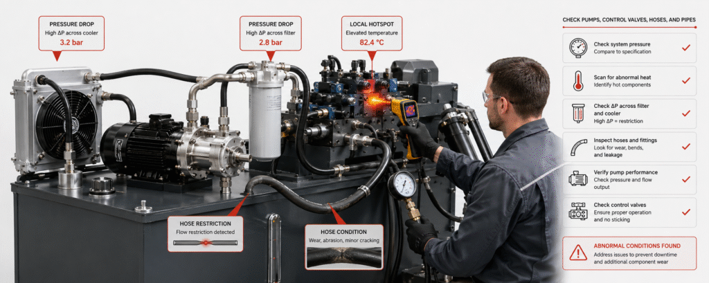
Abnormal pressure loss in the pump, valve block, or piping can cause the system to generate excessive heat again.
The hydraulic pump should be checked for:
- New or unusual noise
- Increased pump housing temperature
- Reduced output flow after the oil becomes hot
- Longer pressure-building time
- Suction-line vibration
- Air leakage at the pump inlet
- Increased case-drain flow
A pump may still reach the required pressure while losing volumetric efficiency. As internal leakage increases, more input power is converted into heat rather than useful flow.
Control valves should be inspected for abnormal local temperature, especially relief valves, proportional valves, flow-control valves, counterbalance valves, and pressure-reducing valves.
If one valve body or the nearby return line is significantly hotter than the surrounding components, the circuit may have continuous relief flow, excessive throttling, a sticking spool, or internal leakage.
Hoses and pipes should be inspected for:
- Flattening or crushing
- Excessive bending or twisting
- Hardened, cracked, or swollen hoses
- Loose fittings
- Restricted quick couplings
- Increased return pressure
- Abnormal pressure drop across filters or coolers
- Routing close to engines, exhaust pipes, or other heat sources
A hose can look acceptable externally while still being restricted internally. A damaged inner layer, incorrect hose size, or partially connected quick coupling may increase resistance and create heat.
Where hoses or components are installed close to high-temperature equipment, inspect heat shields, insulating sleeves, protective guards, and routing clearances. Damaged insulation should be repaired before the hose material begins to harden or deteriorate.
Test Temperature Alarms and Protection Functions
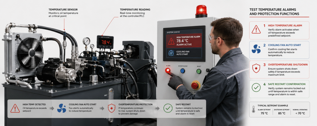
High-temperature alarms and shutdown functions should not be tested only during equipment commissioning.
Summer maintenance should confirm that:
- Temperature sensor readings are accurate
- The cooling fan starts at the correct temperature
- The cooling-water control valve opens correctly
- The early warning alarm is activated
- The overtemperature shutdown function works
- The equipment can restart safely after temperature recovery
- Temperature and alarm records are stored correctly
The displayed temperature should be compared with a calibrated reference instrument when possible. A damaged sensor, poor mounting position, wiring problem, or controller error may cause an inaccurate reading.
Alarm temperatures should not be raised simply to reduce interruptions. This may temporarily prevent the alarm from appearing, but it does not reduce the real oil temperature.
Operating above the intended temperature limit accelerates oil oxidation and can shorten the service life of seals, hoses, solenoid coils, electrical connectors, and other hydraulic components.
If the system repeatedly reaches the high-temperature alarm, the correct response is to identify why heat generation has increased or cooling capacity has fallen. Adjusting the alarm setting only hides the symptom.
Summer Hydraulic System Maintenance Checklist
| Inspection Category | Main Items to Check | Warning Signs |
|---|---|---|
| Temperature and performance | Ambient temperature, reservoir temperature, cooler temperature difference, cycle time | Higher stabilized temperature, faster temperature rise, slower hot-running performance |
| Hydraulic oil | Oil level, color, odor, foam, emulsification, contamination | Abnormal oil loss, oxidation, water contamination, air entrainment |
| Filters and reservoir | Filter differential pressure, clogging indicator, breather, reservoir water | Blocked filter, bypass operation, recurring contamination |
| Cooling system | Cooler fins, fan, temperature switch, cooling water, ventilation | Reduced heat rejection, hot-air recirculation, scale buildup |
| Pumps, valves, and piping | Pump noise, valve temperature, hose condition, return pressure | Internal leakage, continuous relief flow, restriction, excessive backpressure |
| Protection functions | Temperature sensor, fan start, warning alarm, shutdown | Inaccurate readings, failed control logic, unsuitable alarm settings |
Conclusion
Preventing hydraulic overheating from returning requires more than a one-time repair or the replacement of a single component.
Effective summer maintenance should include regular temperature and performance records, clean hydraulic oil, properly maintained filters and breathers, reliable cooler operation, and periodic inspection of pumps, valves, hoses, and protection systems.
If the stabilized oil temperature gradually rises, filters become blocked frequently, cooler temperature performance declines, or the machine slows down after warming up, the cause should be investigated before a high-temperature alarm occurs.
The purpose of summer maintenance is not only to lower the current oil temperature. It is to identify changes in efficiency, contamination, leakage, and cooling capacity before they develop into repeated shutdowns, external leakage, or expensive component damage.