A hydraulic system that cannot build or maintain pressure will usually show obvious performance problems: cylinders move weakly, actuators slow down under load, lifting capacity drops, or the machine cannot complete its normal working cycle.
Pressure loss does not always mean the hydraulic pump has failed. The actual cause may be a relief valve that is bypassing oil, internal leakage inside a cylinder or valve, air in the hydraulic fluid, worn pump components, or an external leak somewhere in the circuit.
The fastest way to find the problem is to first identify how the pressure is being lost, then test the system step by step instead of replacing components at random.
Identify How the Hydraulic System Is Losing Pressure
Before checking components, observe when the pressure problem occurs. Most hydraulic pressure-loss problems can be divided into three situations.
The Hydraulic System Cannot Build Pressure
In this case, system pressure remains below the expected value even when the actuator reaches a load condition. The machine may move slowly or produce very little force.
Typical causes include a pump that cannot generate enough flow under load, an incorrectly adjusted relief valve, a relief valve stuck open, severe internal leakage, or insufficient oil reaching the pump.
Hydraulic Pressure Drops Under Load
The system may appear normal when operating without resistance, but pressure drops once the cylinder begins lifting, pressing or pushing a real load.
This often indicates pump wear, internal leakage or a valve bypassing oil. A component may still work at low pressure but lose too much flow when the required pressure increases.
Hydraulic Pressure Cannot Hold
The system may initially reach the correct pressure but then gradually lose it while the actuator is supposed to remain stationary.
This usually points toward internal leakage across a cylinder piston seal, directional valve, check valve or another load-holding component. External leakage can also cause the same symptom if oil is visibly escaping from the system.
Identifying which of these three conditions is occurring can narrow the diagnosis significantly.
How to Diagnose Hydraulic System Pressure Loss
A structured diagnosis is usually faster and more reliable than replacing the pump or adjusting the relief valve immediately. The goal is to identify whether pressure is being lost because the system cannot generate enough hydraulic power, oil is bypassing internally, or flow is being restricted somewhere in the circuit.
Step 1: Check Oil Level, Condition and External Leaks
Start with the simplest checks. Confirm that the reservoir contains enough hydraulic oil and inspect hoses, fittings, cylinders, valves and pump connections for visible leakage.
A low oil level can allow the pump to draw air instead of a steady oil supply, which may cause unstable pressure, noise and slow actuator response. External leaks should be repaired before repeatedly adding oil, because refilling the reservoir does not correct the original problem.
Also check the oil condition. Foamy or cloudy oil can indicate aeration, while heavily contaminated oil may affect valves and other close-tolerance hydraulic components.
Step 2: Measure the Actual Hydraulic System Pressure
Install a suitable pressure gauge at an appropriate point in the circuit and compare the measured pressure with the expected working pressure.
Observe the system under different conditions. Does it fail to build pressure from the beginning? Does the pressure reach the correct value without load but drop when the cylinder begins working? Or does the pressure fall after the actuator stops moving?
These pressure readings help determine which part of the circuit should be checked next.
Pressure measured at the pump outlet may also be different from the pressure reaching the actuator because valves, fittings, hoses and other components create pressure loss.
Step 3: Check the Pressure Relief Valve
The relief valve limits maximum hydraulic system pressure by directing oil back to the reservoir when pressure reaches its set value.
If the valve is adjusted too low, contaminated, damaged or stuck partially open, oil may return to the tank before the system reaches the required working pressure. This can make the entire hydraulic system appear weak even when the pump is still functioning correctly.
The relief setting should be verified with a pressure gauge and compared with the system design requirement. Any adjustment must remain within the rated pressure of the pump, cylinder, valves, hoses and fittings.
Increasing the relief setting simply to obtain more force is not a safe solution if the actual problem is an undersized cylinder or internal leakage.
Step 4: Evaluate the Hydraulic Pump
If the relief valve is operating correctly, check whether the hydraulic pump can still supply adequate flow at the required pressure.
A worn pump may continue to work at low load but lose too much flow internally as pressure increases. As a result, the system may appear normal without resistance but lose pressure and speed when the machine starts working.
Typical signs include reduced actuator speed, low pressure under load, excessive pump noise, abnormal temperature and unstable pressure readings.
However, pump replacement should not be based on low pressure alone. Internal leakage elsewhere in the circuit can create similar symptoms.
Step 5: Check for Internal Leakage
Internal leakage is a common cause of hydraulic pressure loss when there is no obvious external oil leak.
Oil may bypass internally through worn cylinder piston seals, directional valves, proportional valves, check valves or other control components. Instead of producing useful actuator force, part of the pump flow escapes through the internal leakage path.
A cylinder with worn piston seals, for example, may move normally without load but fail to generate enough force or hold its position under load.
If a cylinder drifts while the control valve is in neutral, the leakage may be inside the cylinder or in the valve controlling it. Isolating sections of the circuit and monitoring pressure can help locate the bypass path.
Step 6: Check for Air Entry and Hydraulic Restrictions
Air in the hydraulic oil can cause unstable pressure, slow or jerky actuator movement, excessive noise and poor system response. Common causes include low oil level, loose suction fittings, damaged suction hoses or incomplete bleeding after maintenance.
The suction side of the pump deserves particular attention because it can draw air into the system without necessarily leaking oil outward.
Restrictions should also be checked. A clogged filter, damaged suction hose, undersized pipe, contaminated valve or partially blocked passage can reduce the amount of oil reaching the pump or actuator.
Pressure measurements taken at different locations can help identify an abnormal pressure drop across a restriction.
A practical diagnosis sequence is:
Oil Level & Condition → External Leaks → Pressure Measurement → Relief Valve → Pump → Internal Leakage → Air & Restrictions
How to Fix Hydraulic System Pressure Loss
The correct repair depends on the cause identified during diagnosis.
A relief-valve problem may require cleaning, adjustment or replacement. A worn pump may need repair or replacement if internal leakage prevents it from maintaining the required flow at working pressure.
Internal leakage in a hydraulic cylinder may require replacement of the piston seals, while excessive leakage through a control valve may require valve repair or replacement. Air-entry problems require repairing suction-side leaks and properly bleeding the hydraulic system.
Clogged filters, damaged hoses and heavily contaminated oil should also be corrected according to the actual condition of the system.
After repairs, the hydraulic system should be tested again under the real operating load rather than only at idle.
Common Hydraulic Pressure-Loss Mistakes
One common mistake is assuming that every low-pressure problem is caused by the hydraulic pump. Pumps are important, but relief valves, cylinders and control valves can create very similar symptoms.
Another mistake is increasing the relief-valve setting before finding the cause. This may temporarily increase pressure but can overload components that were not designed for the higher operating pressure.
It is also important not to rely on pressure alone. A system may show pressure on a gauge but still lack sufficient usable flow under load.
The better approach is to measure pressure, observe when the pressure loss occurs and identify where oil is bypassing or being restricted.
Conclusion: Diagnose the Hydraulic System Before Replacing Components
Hydraulic pressure loss is usually caused by one of several basic problems: insufficient pump output, incorrect relief-valve operation, internal leakage, external leakage, air in the oil or excessive flow restriction.
The most important first step is determining whether the system cannot build pressure, loses pressure under load, or cannot hold pressure after reaching the target value.
Once that behavior is identified, a structured diagnosis can narrow the problem quickly:
Oil & Leaks → Pressure Measurement → Relief Valve → Pump → Internal Leakage → Air & Restrictions
This approach helps reduce unnecessary component replacement and makes it easier to restore normal hydraulic system force, speed and reliability.
Need Help with a Hydraulic System?
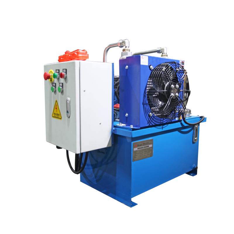
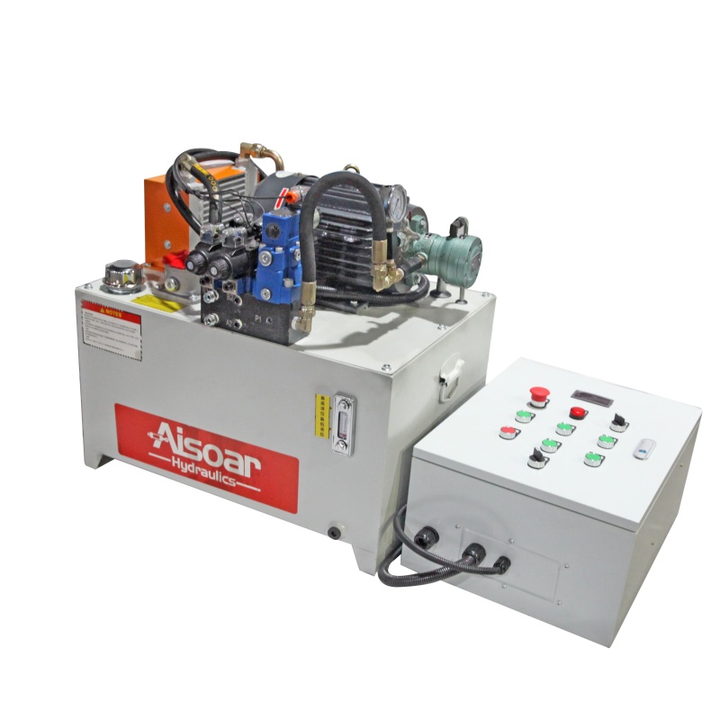
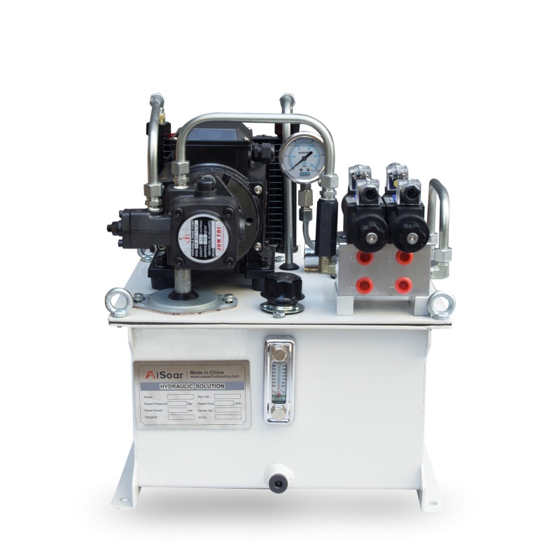
AISOAR provides customized hydraulic power units and hydraulic system solutions for industrial and mobile equipment. System configurations can be developed according to required pressure, flow, actuator specifications, duty cycle and control requirements.
For an OEM project or hydraulic system evaluation, providing the system working pressure, pump flow, actuator specifications, circuit information and a description of the operating problem can help our engineering team evaluate the system more efficiently.