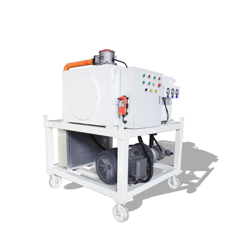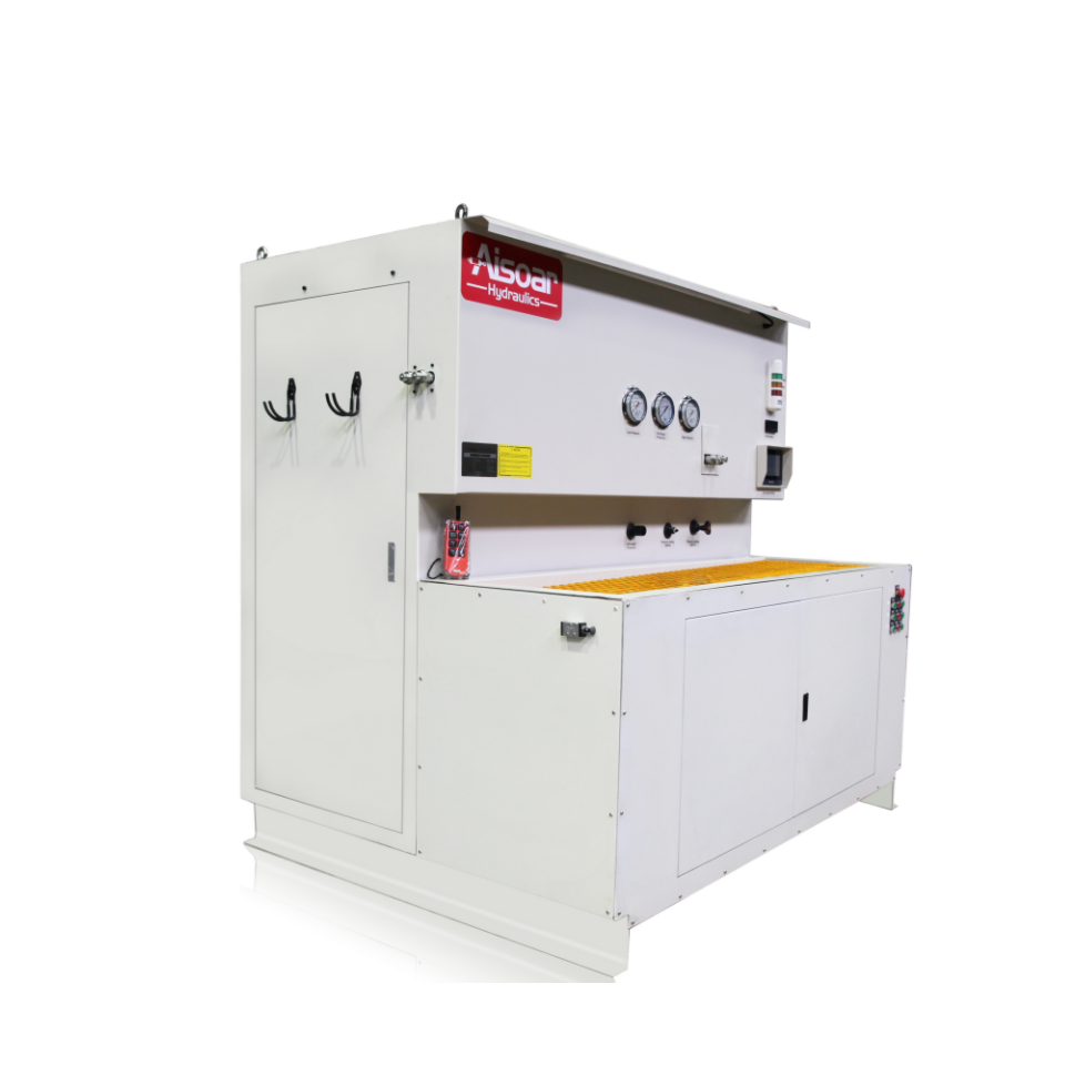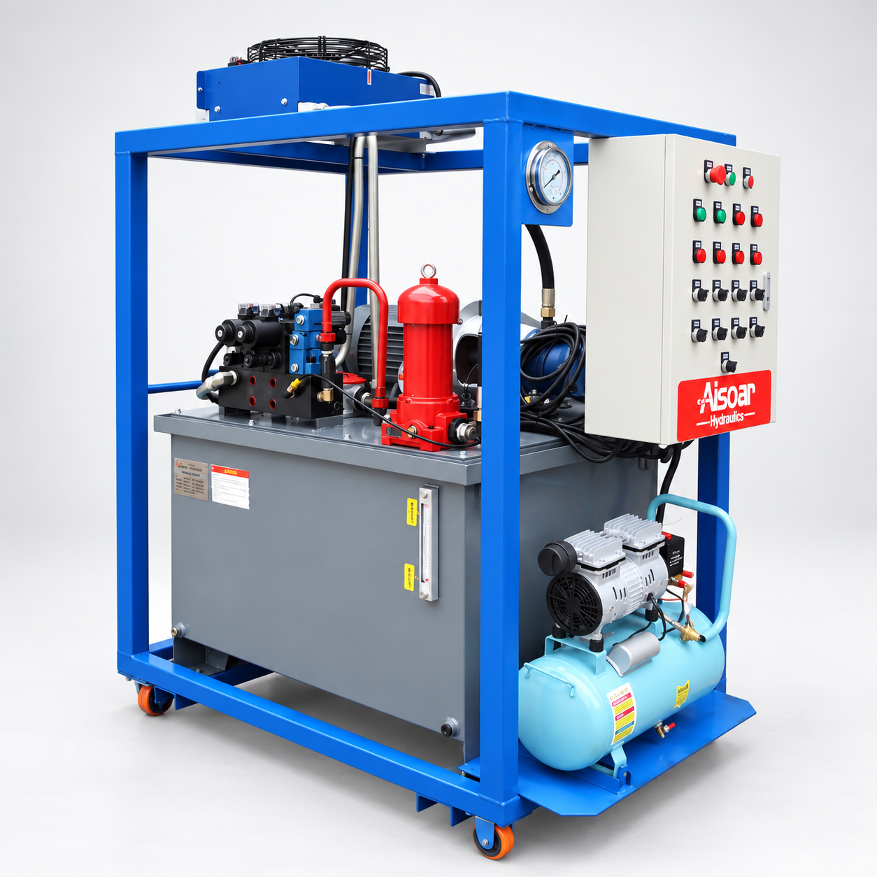
A hydraulic test bench intentionally creates conditions that can include high pressure, high flow, mechanical movement, stored hydraulic energy, hot oil, rotating components, and component failure. Safety therefore cannot be treated as an accessory added after the hydraulic circuit and machine structure have already been designed.
A better approach is to start with the hazards created by the actual test procedure and then build several layers of protection around them. ISO 12100 follows this risk-assessment and risk-reduction approach for machinery design, while ISO 4413 addresses significant hazards associated with hydraulic fluid power systems and components.
For a hydraulic test bench, this normally means considering pressure containment, mechanical guarding, hydraulic pressure protection, stored-energy control, safety-related controls, emergency stopping, and safe maintenance access as one integrated system.
Start with the Test Hazard, Not the Guard
A common mistake is to decide that a test bench “needs a safety cover” before identifying what the cover is actually intended to protect against. The correct guarding concept depends on the component being tested and the way failure could occur.
During cylinder testing, the main hazards may include cylinder movement, fixture failure, released mechanical force, hose or fitting failure, and oil discharge. A pump or hydraulic motor test bench can introduce rotating shafts and couplings in addition to pressurized oil, while a valve or hose test bench may place greater emphasis on fluid release and component rupture.
This is why the first design task should be a risk assessment covering normal testing, setup, component loading, connection, depressurization, maintenance, foreseeable misuse, and possible component failure. ISO 12100 specifically provides a methodology for identifying hazards, estimating and evaluating risk, and reducing those risks throughout machinery design and use.
A guard should then be designed around the identified hazard rather than simply around the outside dimensions of the machine.
How Should Guarding Be Designed?
Physical guarding is intended to separate the operator and other personnel from a hazardous area during testing. Depending on the test bench, this may involve fixed panels, access doors, enclosed test chambers, shields around rotating components, or a combination of these methods.
The guarding must also match the possible direction of the hazard. A transparent viewing panel, for example, may improve visibility, but its material, thickness, mounting method, and location must be appropriate for the risk being controlled. A large hydraulic cylinder test area may require a different enclosure concept from a compact valve test station.
In the United States, OSHA’s general machine-guarding requirement calls for one or more guarding methods to protect operators and other employees from machine hazards, and OSHA’s hydraulic press guidance also emphasizes that guards should not themselves create additional hazards.
For test equipment, guarding should also support the actual workflow. Operators still need reasonable access for loading components, changing fixtures, connecting hoses, and performing inspection. A guard that is so inconvenient that operators are tempted to bypass it is not a good engineering solution.
Guarding and Safety Interlocks Should Work Together
An access door can provide physical separation, but on an automated or high-pressure test bench it may also need to interact with the machine control system.
For example, the design may prevent a high-pressure test from starting while the test-area door is open. If the door is opened during a hazardous test stage, the safety system may need to stop the relevant operation and move the machine toward a defined safe condition.
The important point is that the response should be determined by the risk assessment. Simply connecting a normal limit switch to a PLC input does not automatically create an adequate safety function. ISO 13849-1:2023 provides a methodology for designing and integrating safety-related parts of control systems, including electrical, hydraulic, pneumatic, and mechanical technologies, but it does not prescribe one universal performance level for every application.
This distinction is especially important for PLC-controlled test benches. The normal machine-control program and the safety-related control functions should not automatically be treated as the same thing.
How Should Hydraulic Pressure Protection Be Designed?
The design should consider both the required test pressure and foreseeable transient conditions. Pressure-limiting devices should prevent the hydraulic system from being intentionally driven beyond its designed operating envelope, while the test procedure should avoid creating unnecessary pressure spikes or trapped high-pressure sections.
As a general engineering principle, the safe working pressure of individual components should not be exceeded by the anticipated system pressure. OSHA(Occupational Safety and Health Administration) makes this requirement explicit for hydraulic equipment on mechanical power presses, while ISO 4413 provides broader safety requirements for hydraulic systems and components.
Pressure protection can also require more than one level. The normal control system may regulate the required test pressure, while an independent pressure-limiting function provides protection if the normal control fails. The exact architecture depends on the risk assessment, pressure level, hydraulic circuit, and applicable safety requirements.
Stored Hydraulic Energy Must Be Considered
Stopping the pump does not necessarily mean that a hydraulic test bench is safe to open.
Pressure can remain trapped in a cylinder chamber, hose, accumulator, manifold cavity, test component, or isolated section of pipe. A loaded hydraulic cylinder can also contain mechanical energy even when the power unit is no longer running.
The machine should therefore have a defined method for moving from the test condition to a safe access condition. This may include controlled depressurization, confirmation that pressure has fallen to an acceptable level, and prevention of unintended movement before an operator can enter the test area.
This is particularly important when an interlocked guard is used. Opening the door should not merely remove electrical power while significant hydraulic pressure remains trapped behind the guard.
For maintenance and servicing, hazardous energy control must also be considered separately from normal operating controls. OSHA’s guidance on machinery emphasizes the relationship between machine guarding and hazardous-energy control during servicing activities.
Emergency Stop Is a Safety Function, Not a Normal Stop Button
A hydraulic test bench should also consider how hazardous operation can be stopped when an abnormal situation occurs.
ISO 13850 establishes functional requirements and design principles for machinery emergency-stop functions, while IEC 60204-1 covers electrical, electronic, and programmable electronic equipment used on machines and includes requirements related to emergency stopping and control circuits.
However, an emergency stop should not be treated as a substitute for guarding, pressure protection, or a properly designed safety system. ISO 13850 itself distinguishes the emergency-stop function from other protective measures such as shielding or limiting motion.
For a hydraulic test bench, the required response may involve stopping hydraulic power, moving valves to an appropriate state, preventing further pressure increase, or stopping hazardous mechanical movement. The safest response is application-specific because immediately removing power is not always the same as safely eliminating stored hydraulic energy.
Safety Monitoring Should Support the Pressure Protection System
Sensors can also play an important role in confirming whether the system is operating inside its intended test envelope.
Pressure sensors may be used to monitor actual test pressure, while temperature sensors can detect abnormal oil temperature. Door position, fixture position, or other status signals may also be incorporated into the control architecture where required by the risk assessment.
The important distinction is that measurement and safety are not automatically the same function. A pressure transducer used to generate a test report does not necessarily constitute an independent overpressure protection device. Likewise, an HMI warning is not the same as a safety-related protective function.
The design should therefore distinguish between instrumentation used to measure the test and devices or control functions used to protect people and equipment. Where a function is safety-related, the required architecture and reliability should be determined through the machinery risk assessment and the applicable safety-control methodology.
Safety Design Should Cover the Whole Test Cycle
A hydraulic test bench is not hazardous only while it is at maximum pressure. Loading and unloading heavy components, changing fixtures, connecting hoses, performing low-pressure circulation, starting a test, releasing pressure, and servicing the machine can all create different risks.
A useful safety review should therefore follow the complete operating sequence rather than examining only the high-pressure hydraulic schematic.
| Test Stage | Typical Safety Focus |
|---|---|
| Component loading | Weight, lifting, fixture stability and pinch points |
| Hose / adapter connection | Correct connection and pressure rating |
| Pre-test setup | Guard position, fixture condition and circuit configuration |
| Pressure testing | Pressure containment, guarding and overpressure protection |
| Dynamic testing | Mechanical motion, rotating parts and automated sequence |
| Test completion | Controlled depressurization and confirmation of safe state |
| Component removal | Residual pressure, hot surfaces and mechanical support |
| Maintenance | Isolation and hazardous-energy control |
Looking at the entire cycle also makes it easier to identify situations where an operator may need to enter the guarded area and what conditions must be satisfied before access is allowed.
Applicable Standards Depend on the Machine and Market
There is no single standard that replaces a complete risk assessment for every hydraulic test bench. ISO 12100 provides the general machinery risk-assessment framework, ISO 4413 addresses hydraulic fluid-power safety, ISO 13850 covers emergency-stop design principles, ISO 13849-1:2023 addresses safety-related control systems, and IEC 60204-1 addresses electrical equipment of machinery.
Additional requirements may apply depending on the test bench type, country, industry, pressure equipment involved, electrical system, or customer specification. In the United States, for example, OSHA’s general machine-guarding provisions may also be relevant to workplace use.
For this reason, standards should be treated as part of the design input rather than as a checklist added after the machine has been built.
Conclusion
Safety design for a hydraulic test bench requires more than installing a relief valve and surrounding the machine with a metal enclosure. The test bench should be designed around the hazards created by the component, test pressure, hydraulic energy, mechanical movement, operating sequence, and operator interaction.
A strong safety concept combines risk assessment, appropriate guarding, pressure-rated components, overpressure protection, controlled depressurization, safety-related controls, emergency stopping, and safe maintenance access. These measures should work together rather than being treated as independent options.
The most useful design question is therefore not:
“What safety accessories should be added to the test bench?”
It is:
“What can happen during each stage of this test, and what independent layers of protection are needed to reduce that risk?”
That approach produces a hydraulic test bench that is not only capable of reaching the required pressure and flow, but also designed around safe and controlled testing.